Straight handle baton with mushroom cap

a mushroom cap and baton technology, applied in the field of batons, can solve the problems of difficult to find and roll down an incline, and achieve the effect of better retention of the baton

a mushroom cap and baton technology, applied in the field of batons, can solve the problems of difficult to find and roll down an incline, and achieve the effect of better retention of the baton

US20050083679A1Inactive Publication Date: 2005-04-21MACIEROWSKI GLENN E +1

Image

  • Straight handle baton with mushroom cap
  • Straight handle baton with mushroom cap
  • Straight handle baton with mushroom cap

Examples


Embodiment Construction

[0045] The present invention is a straight baton with a mushroom cap. The invention disclosed herein is, of course, susceptible of embodiment in many different forms. Shown in the drawings and described herein below in detail are preferred embodiments of the invention. It is to be understood, however, that the present disclosure is an exemplification of the principles of the invention and does not limit the invention to the illustrated embodiments.

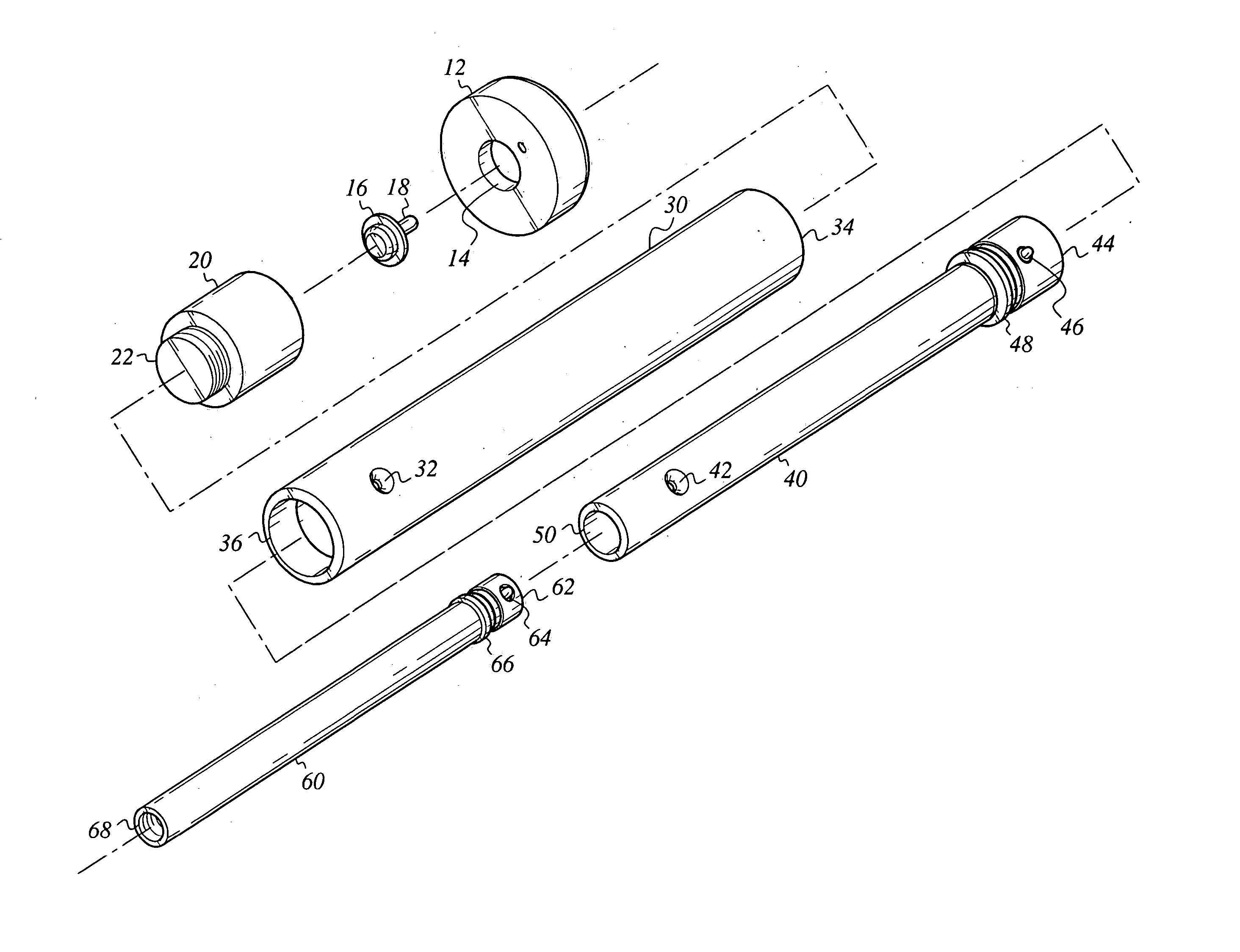
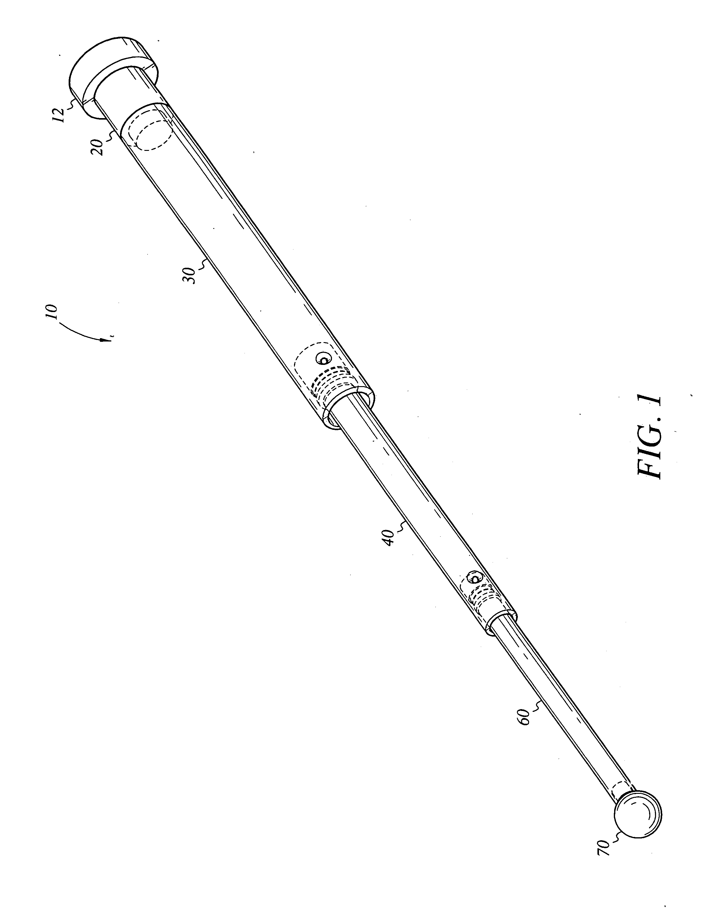
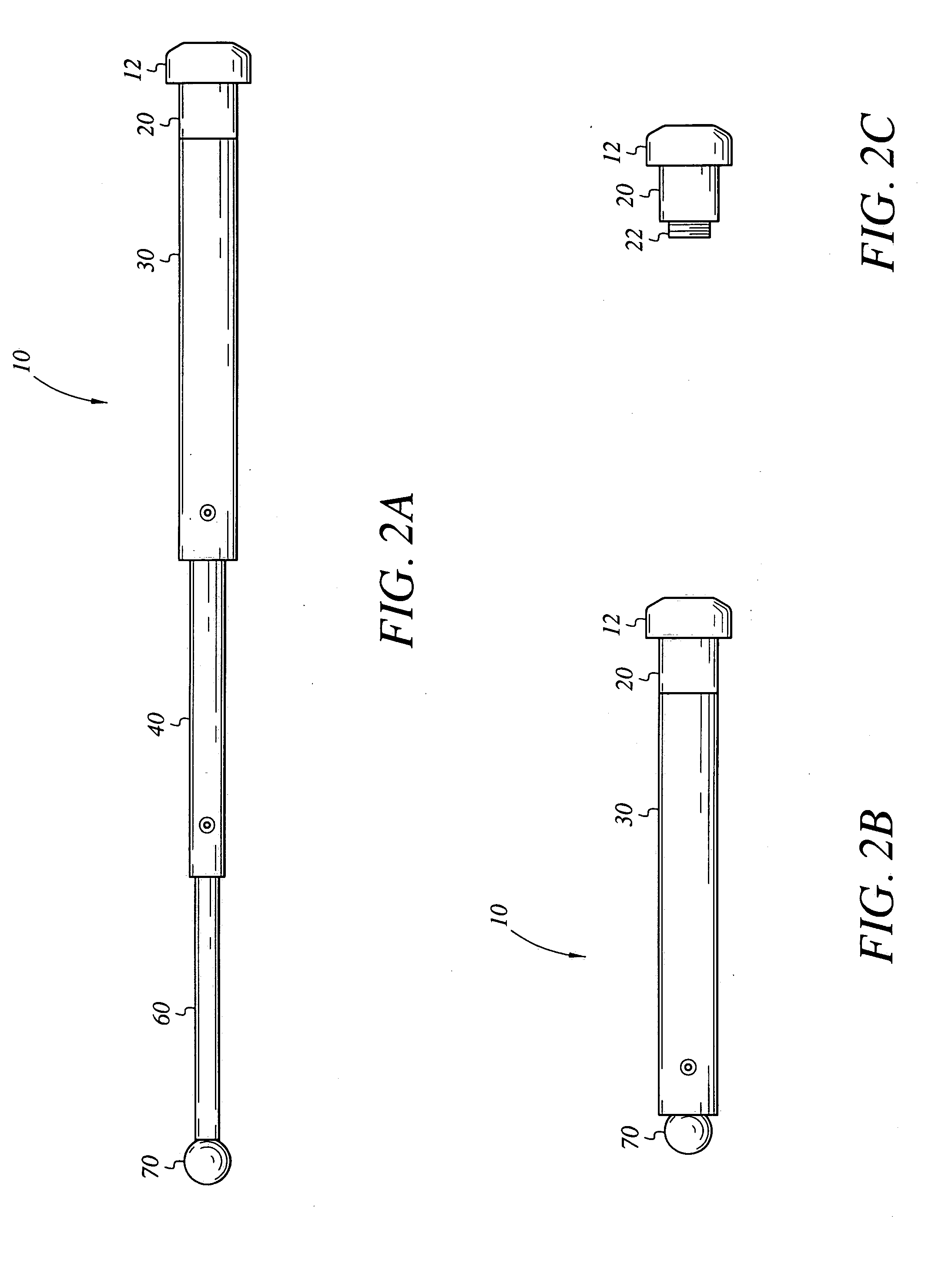
[0046] Referring to the drawings, FIG. 1 shows a straight baton 10 according to the invention. The baton 10 includes a cap 20, multiple shaft sections 30, 40, 60, and a striking end 70. The multiple shaft sections 30, 40, 60 are cylindrically shaped. Each shaft section 30, 40, 60 has predetermined inner and outer diameters, a predetermined length, and opposing ends. The inner diameter of the first shaft section 30 is larger than the outer diameter of the second shaft section 40, and the inner diameter of the second shaft section 40 is lar...


PUM


Abstract

A straight baton includes a bulbous or mushroom shaped cap which releasably receives a light device with a light element, multiple shaft sections including at least first, second, and third shaft sections, and a striking end. The first, second, and third shaft sections are cylindrically shaped, and each shaft section has predetermined inner and outer diameters, a predetermined length, and opposing ends. The inner diameter of the first shaft section is larger than the outer diameter of the second shaft section, and the inner diameter of the second shaft section is larger than the outer diameter of the third shaft section. The first shaft section is configured to enable the second shaft section to releasably retract into or extend out of the first shaft section, and the second shaft section is configured to enable the third shaft section to releasably retract into or extend out of the second shaft section.

Description

BACKGROUND OF THE INVENTION [0001] 1. Field of the Invention [0002] The present invention generally relates to batons and, more particularly, to an expandable straight baton with a mushroom cap that may be converted into an expandable side handle baton. [0003] 2. Description of the Related Art [0004] Law enforcement individuals, such as police officers, security personnel, or the like, commonly carry a number of items with them during their on duty rotations. One of the devices police officers often carry is a baton to offer them assistance during potentially threatening public encounters. During such encounters, the baton may be dislodged from the hands of the police officer and, being cylindrically shaped, may roll down an incline and be difficult to find after the encounter. It would be desirable for law enforcement individuals to have access to a baton with a handle that facilitates the ability to find the baton quickly after being dropped and / or dislodged. It would also be desi...

Claims


Application Information

Patent Timeline
21 Apr 2005
Publication
US20050083679A1
IPC
A45B3/02; F41B15/02
CPC
F41B15/027
Inventors
MACIEROWSKI, GLENN E.; GOLESKIE, ERIC J.