AI technical title is built by PatSnap AI team. It summarizes the technical point description of the patent document.
a shadowless illumination and shadowless technology, applied in the field of smart shadowless illumination systems, can solve the problems of human intervention and not always available, and achieve the effect of eliminating human intervention
Inactive Publication Date: 2005-04-21
FILEP ZOLTAN
View PDF6 Cites 23 Cited by
Summary
Abstract
Description
Claims
Application Information
AI Technical Summary
This helps you quickly interpret patents by identifying the three key elements:
Problems solved by technology
Method used
Benefits of technology
Benefits of technology
[0005] The invention is directed to eliminate human intervention in shadowless illumination systems and to create optimal lighting conditions.
[0010] To eliminate shadow in a certain target position, as analyzed above, it is necessary to make sure, that the primary visual field—the target area—is better illuminated than the secondary visual field—the unimportant area.
[0012] 1. Dynamic—to move the lamp, so there is no obstacle between the light-source and the target.
[0021] The following examples will use a direct targeting procedure. If direct targeting cannot be used because of different reasons, indirect targeting will be used. That makes the system more expensive, but still possible.
Problems solved by technology
These controls need human intervention, what is not always available.
Method used
Image
Click on the blue label to locate the original text in one second.
Reading with bidirectional positioning of images and text.
Examples
Embodiment Construction
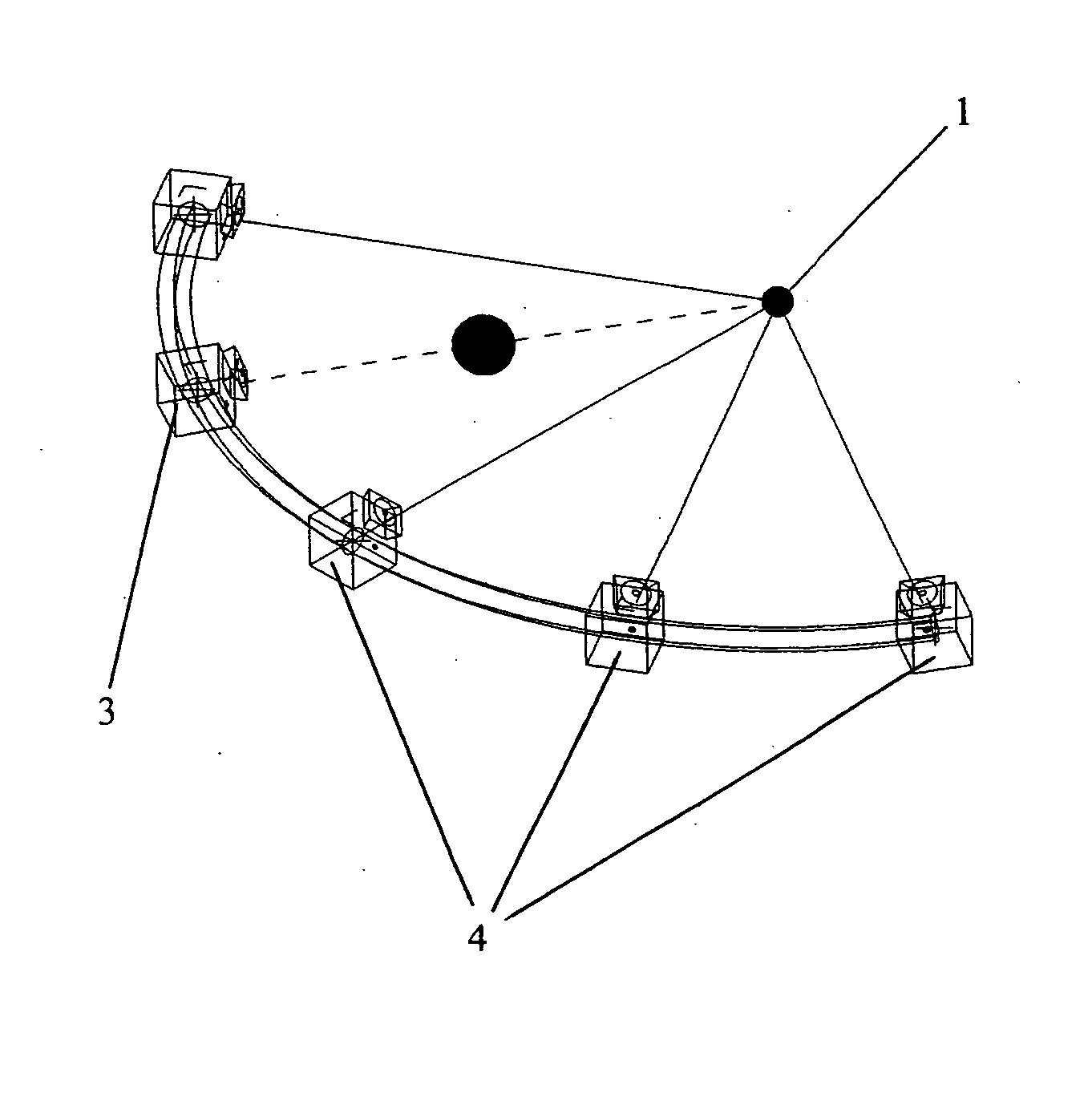
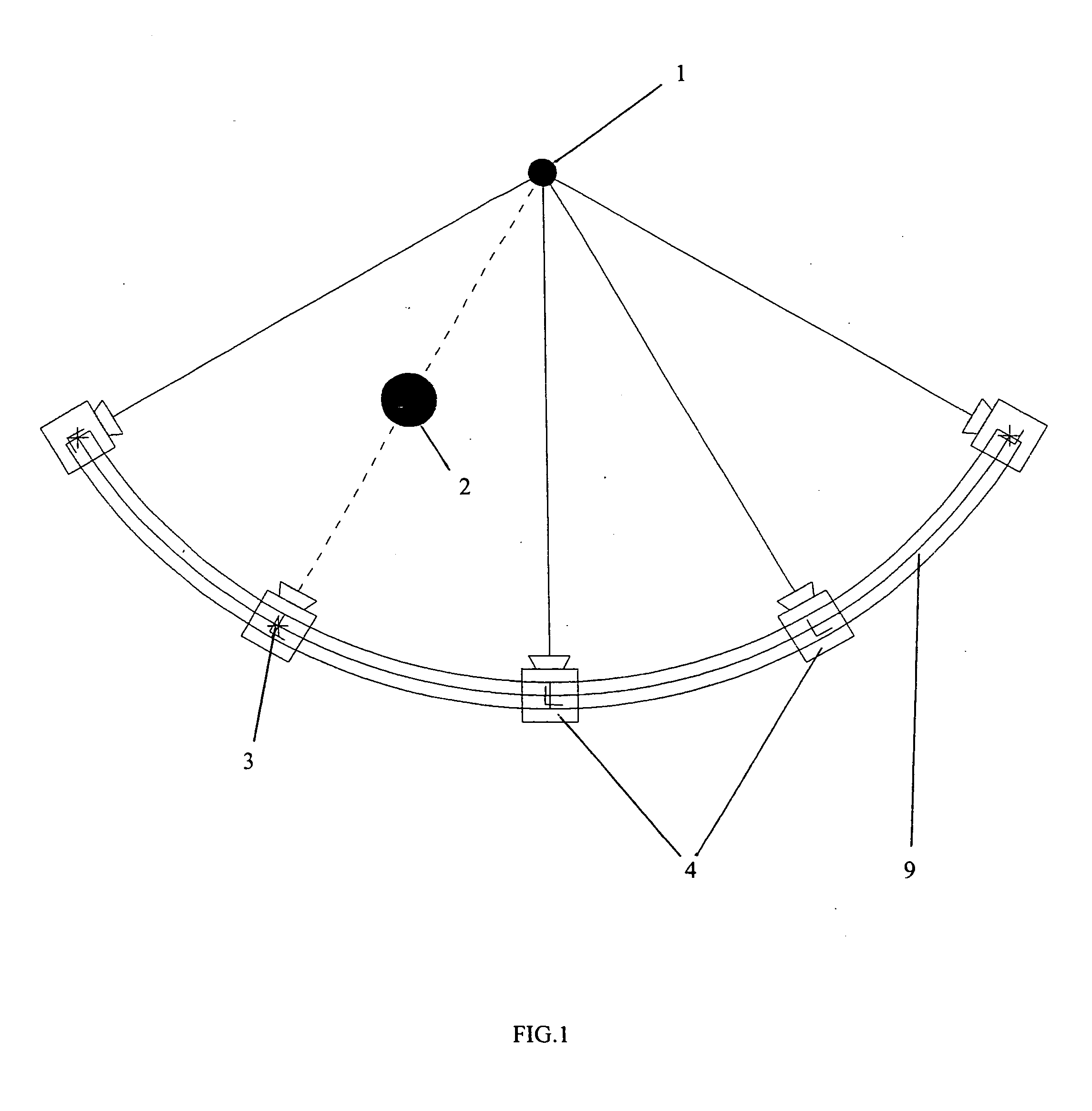
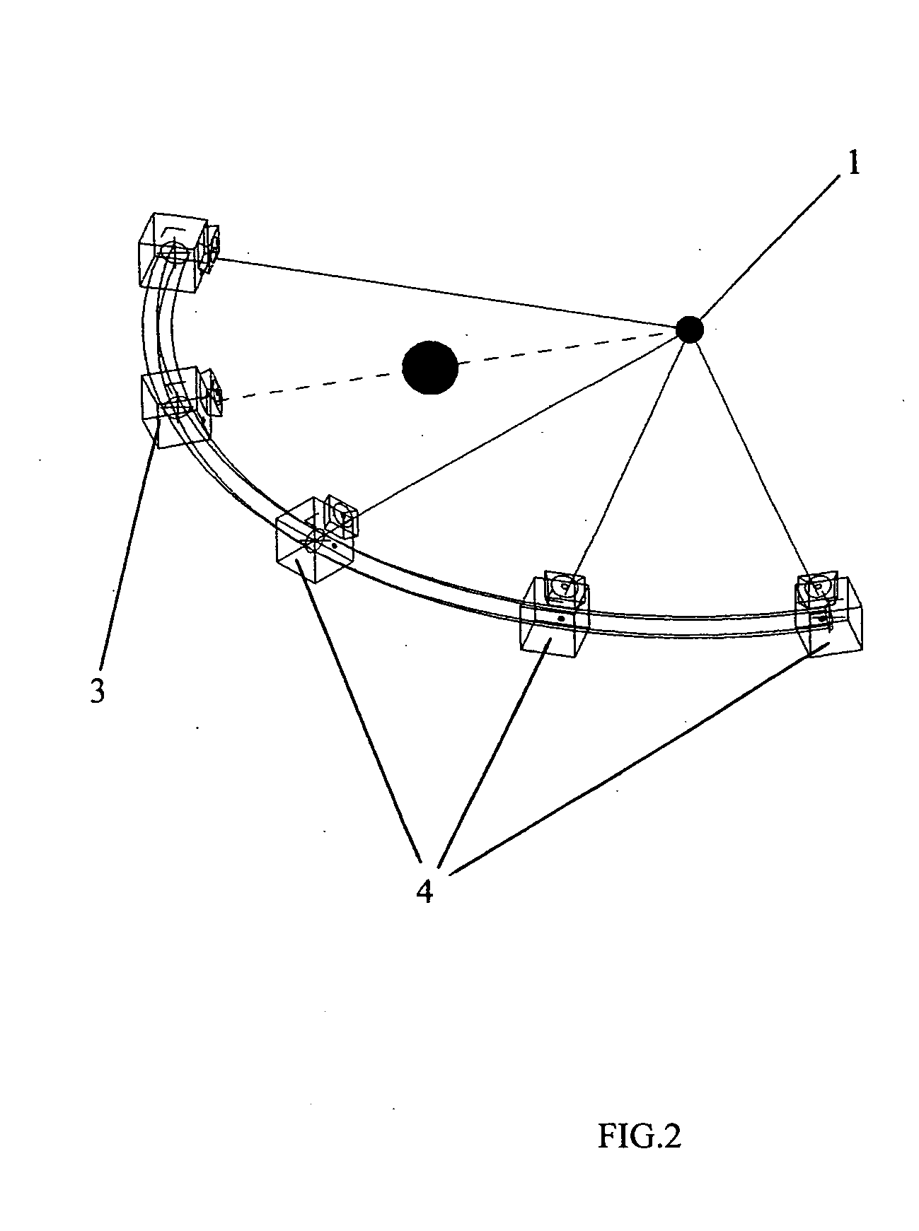
[0038] In all drawings: [0039]1—emitter target area / work zone [0040]2—obstacle, shadow creating object [0041]3—invalid light / position [0042]4—valid light / position [0043]5—light / lamp [0044]6—validation sensor light [0045]7—direction sensor right [0046]8—direction sensor left [0047]9—rail.
[0048] The static solution for the shadowless illumination system is represented in FIG. 1, FIG. 2, FIG. 3 and FIG. 4.
[0049] The target area can be marked directly or indirectly. The emitter 1 is used to mark directly the target area. The obstacle 2 is blocking the visibility for lamp 3, the fact is sensed by the sensor 6, what is turning the lamp 5 off. The other lamps, in position 4 have a visibility on 1, so they are on.
[0050] The lamps are mounted on the rail 9 and they are oriented and focused on 1.
[0051] The dynamic solution for the shadowless illumination system, with a single-axis motion control, is showed in FIG. 5, FIG. 6, FIG. 7 and FIG. 8.
[0052] The target area can be marked directly...
PUM
Abstract
What is new in this invention, it is the complete automation of the light assembly positioning or selection. Using sensors and robotics, human intervention became completely unnecessary. Once the system installed and optimized, human intervention is unnecessary and the system is working independently. The system is sensing the possibility of appearance of shadow for a well-determined area and it is taking measures to avoid it.
Description
REFERENCES CITED U.S. PATENT DOCUMENTS [0001]3,702,928November 1972Alger362 / 233 X4,025,778May 1977Hayakawa240 / 1.44,078,720March 1978Nurnberg236 / 46 R4,200,862April 1980Campbell et al.340 / 825.07 X4,288,844September 1981Fishet et al.362 / 804 X4,365,720December 1982Kaneshiro211 / 874,578,575March 1986Roos250 / 2034,639,838January 1987Kato et al.362 / 334,709,412November 1987Seymour et al.455 / 1284,712,167December 1987Gordin et al.362 / 2334,728,949March 1988Platto et al.340 / 825.374,817,203March 1989Tsurumoto et al.455 / 6034,826,059May 1989Bosch et al.211 / DIG. 14,890,207December 1989Jones362 / 2335,010,459April 1991Taylor et al.362 / 233 X5,031,082July 1991Bierend362 / 233 X5,038,261August 1991Kloos362 / 2865,060,124October 1991Crispin et al.362 / 804 X5,068,767November 1991Koyama362 / 335,072,216December 1991Grange362 / 233 X5,093,769March 1992Luntsford362 / 804 X5,189,412February 1993Mehta et al.340 / 8255,294,915March 1994Owen340 / 5395,526,245June 1996Davis et al.362 / 233FOREIGN PATENT DOCUMENTS [0002]2449994Septem...
Claims
Application Information
Patent Timeline
Application Date:The date an application was filed.
Publication Date:The date a patent or application was officially published.
First Publication Date:The earliest publication date of a patent with the same application number.
Issue Date:Publication date of the patent grant document.
PCT Entry Date:The Entry date of PCT National Phase.
Estimated Expiry Date:The statutory expiry date of a patent right according to the Patent Law, and it is the longest term of protection that the patent right can achieve without the termination of the patent right due to other reasons(Term extension factor has been taken into account ).
Invalid Date:Actual expiry date is based on effective date or publication date of legal transaction data of invalid patent.

