Light tunnel, uniform light illuminating device and projector employing the same

a technology of light illuminating device and projector, which is applied in the direction of non-linear optics, instruments, planar/plate-like light guides, etc., can solve the problem that the components must fit in a limited amount of spa

Inactive Publication Date: 2005-04-21
SAMSUNG ELECTRONICS CO LTD
View PDF11 Cites 79 Cited by
  • Summary
  • Abstract
  • Description
  • Claims
  • Application Information

AI Technical Summary

Problems solved by technology

However, when the uniform light illuminating device is used in a

Method used


Image

  • Light tunnel, uniform light illuminating device and projector employing the same
  • Light tunnel, uniform light illuminating device and projector employing the same
  • Light tunnel, uniform light illuminating device and projector employing the same

Examples


first embodiment

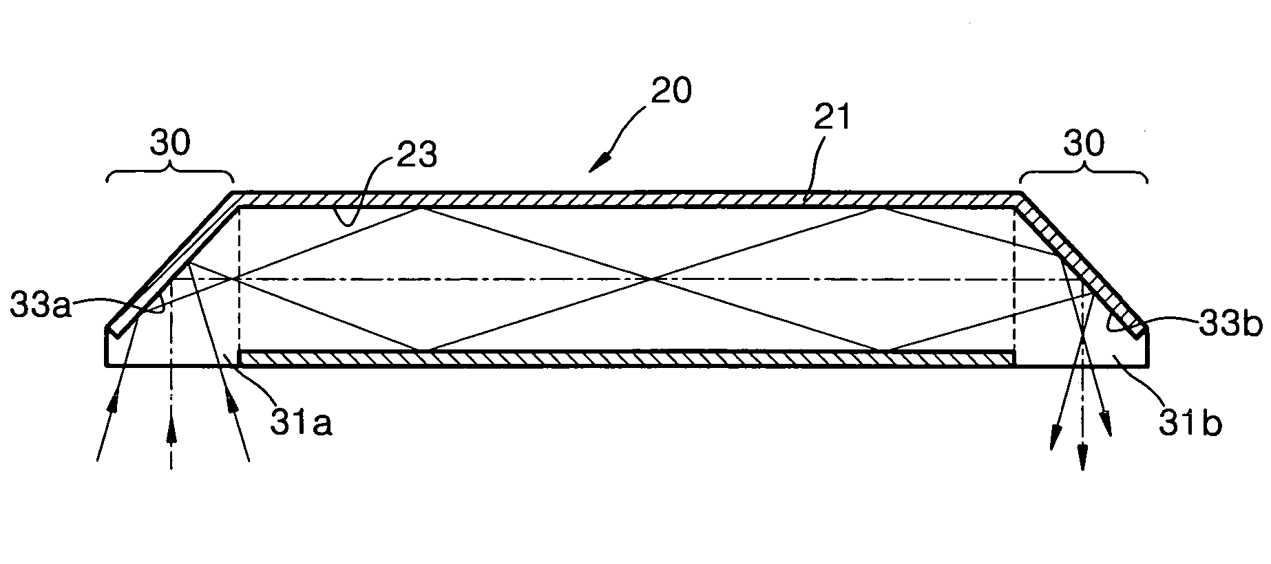
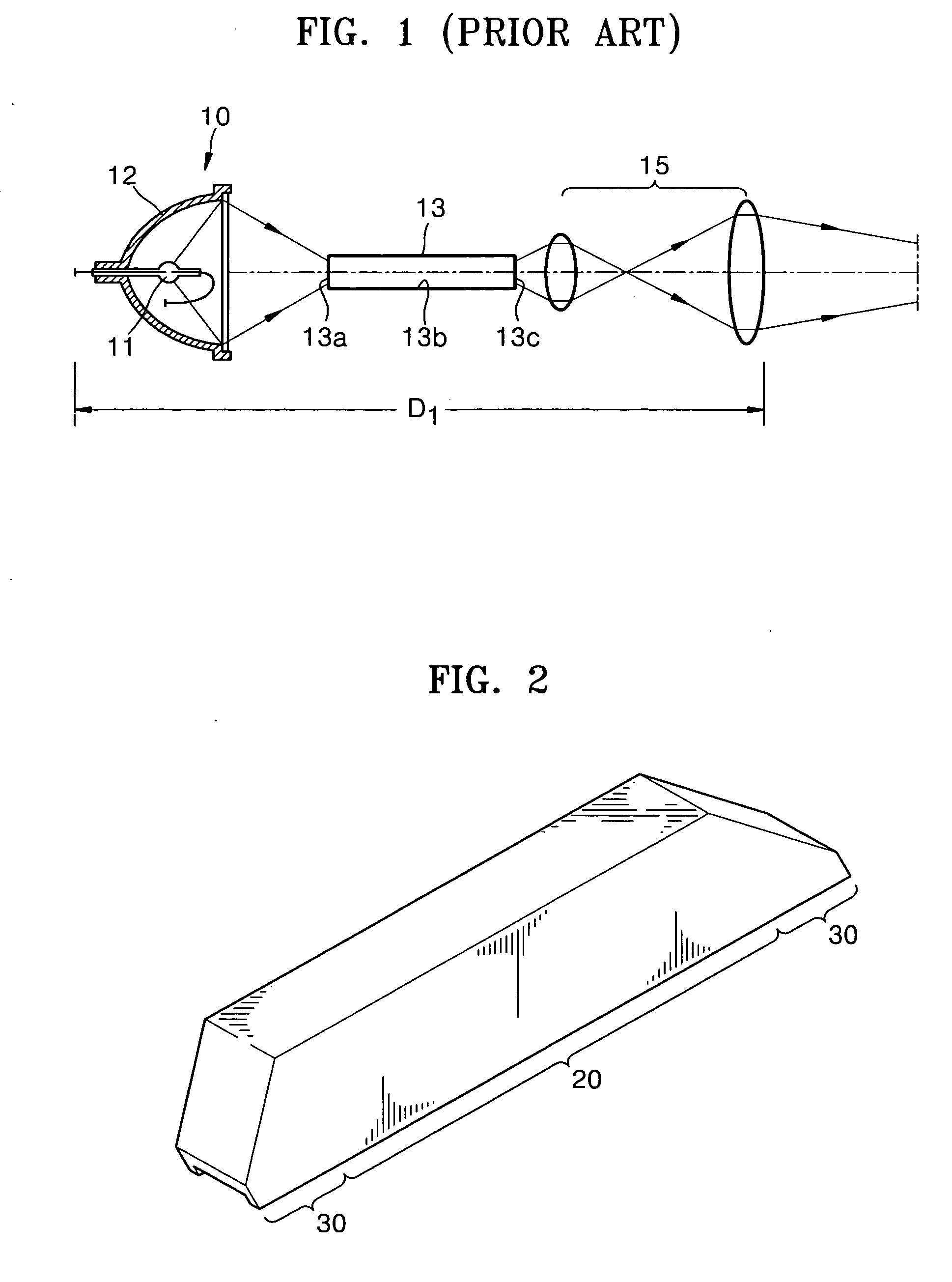
[0026] Referring to FIGS. 2 and 3, a light tunnel according to the present invention includes a guide member 20 for directing incident light rays and outputting a uniform beam of light and an optical path change portion 30 provided at either end of the guide member 20.

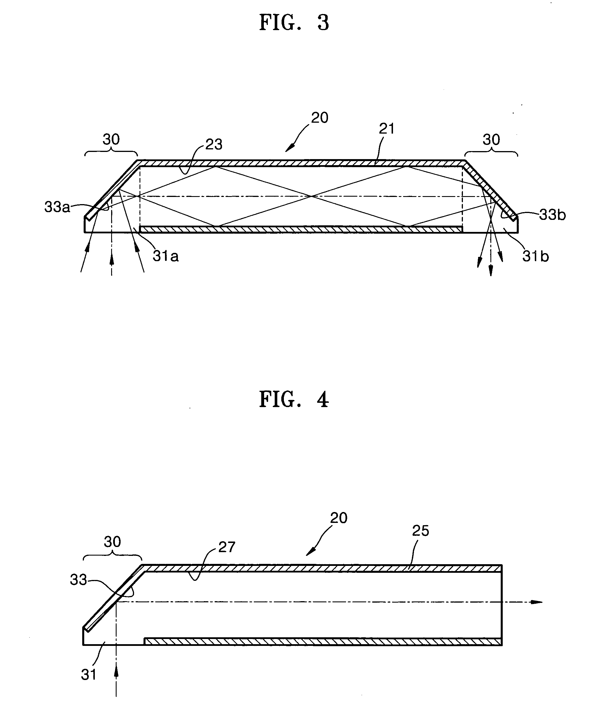
[0027] The guide member 20 includes a mirror case 21 encompassing an inner space in which light travels, and a reflection portion 23 formed on an inner wall of the mirror case 21. Light rays striking the guide member 20 at a predetermined inclination angle are reflected by the reflection portion 23 and proceeds while being scrambled. Thus, the light rays passing through the guide member 20 are merged into a uniform light beam having a beam profile which is different from that of the incident light rays.

[0028] The optical path change portion 30 is provided at either end of the guide member 20 to redirect the path of the incident light rays. The optical path change portion 30 includes first and second opening portions 3...

third embodiment

[0032] Referring to FIGS. 5 and 6, a light tunnel according to the present invention includes a guide member 40 for redirecting incident light rays and outputting a uniform beam of light and an optical path change portion 50 provided at an end portion of the guide member 40.

[0033] The guide member 40 is a glass rod 41 which directs incident light rays at a predetermined angle to be reflected and transported therein. The light rays are reflected inside the guide member 40 when they strike a side wall of the guide member 40 at an angle greater than a critical angle θc due to a difference in refractive index between the glass forming the glass rod 41 and an external medium, for example, air. Accordingly, the light rays traveling through the guide member 40 are reflected to produce a uniform beam of light which differs from the beam profile of the incident light rays.

[0034] Optical path change portions 50 are provided at both end portions of the guide member 40 which redirect the path ...


PUM


Abstract

Provided is a light tunnel including a guide member for guiding an incident light to proceed therein while being reflected by a side wall thereof to merge the incident light into a uniform light beam, and an optical path change portion provided at least one end portion of the guide member inclined at a predetermined angle with respect to an optical axis of an incident light to reflect the incident light and direct a path thereof.

Description

BACKGROUND OF THE INVENTION [0001] This application claims the priority of Korean Patent Application No. 2003-72500, filed on Oct. 17, 2003, in the Korean Intellectual Property Office, the disclosure of which is incorporated herein in its entirety by reference. [0002] 1. Field of the Invention [0003] The present invention relates to a light tunnel for providing a uniform light which has an improved structure enabling a compact optical arrangement, a uniform light illuminating device using the light tunnel, and a projector which employs the light tunnel and the uniform light illuminating device. [0004] 2. Description of the Related Art [0005] In general, projectors provide an image onto a screen by using an illuminating device and an image display device. Image display devices include digital micro-mirror devices (DMDs), transmission type LCDs and reflection type liquid crystal on silicon (LCOSs). A uniform light illuminating device makes light emitted from a lamp have a uniform prof...

Claims


Application Information

Patent Timeline
IPC IPC(8): G02F1/13357F21V8/00G02B6/00G02B6/26G02B6/32G02B6/42G03B21/00G03B21/14
CPCG02B6/0011G02B6/4298G02B6/0096G03B21/208H04N9/3141H04N9/3197
Inventor CHA, YONG-DOK
Owner SAMSUNG ELECTRONICS CO LTD
Why Eureka
Try Eureka