Rotary cutting tool having irregular insert orientation

a cutting tool and rotary cutting technology, applied in the field of rotating tools, can solve problems such as interference with optimal productivity, vibrational harmonics that are objectionable, and flaws in the machined produ

Active Publication Date: 2005-04-21
KENNAMETAL INC
View PDF7 Cites 47 Cited by
  • Summary
  • Abstract
  • Description
  • Claims
  • Application Information

AI Technical Summary

Benefits of technology

[0010] It is a feature of the invention to provide improved elements and arrangements thereof by apparatus for the purposes described which is inexpensive, dependable, and fully effective in accomplishing its intended purposes.

Problems solved by technology

Machining work pieces by rotary cutting tools may cause objectionable vibrational harmonics to occur.
This results in chatter and other phenomena which may cause flaws in the machined product.
It is not desirable to alter rotational speeds of a machine tool and rate of advance speeds of a cutting tool as such steps may interfere with optimal productivity.

Method used


Image

  • Rotary cutting tool having irregular insert orientation
  • Rotary cutting tool having irregular insert orientation
  • Rotary cutting tool having irregular insert orientation

Examples


Embodiment Construction

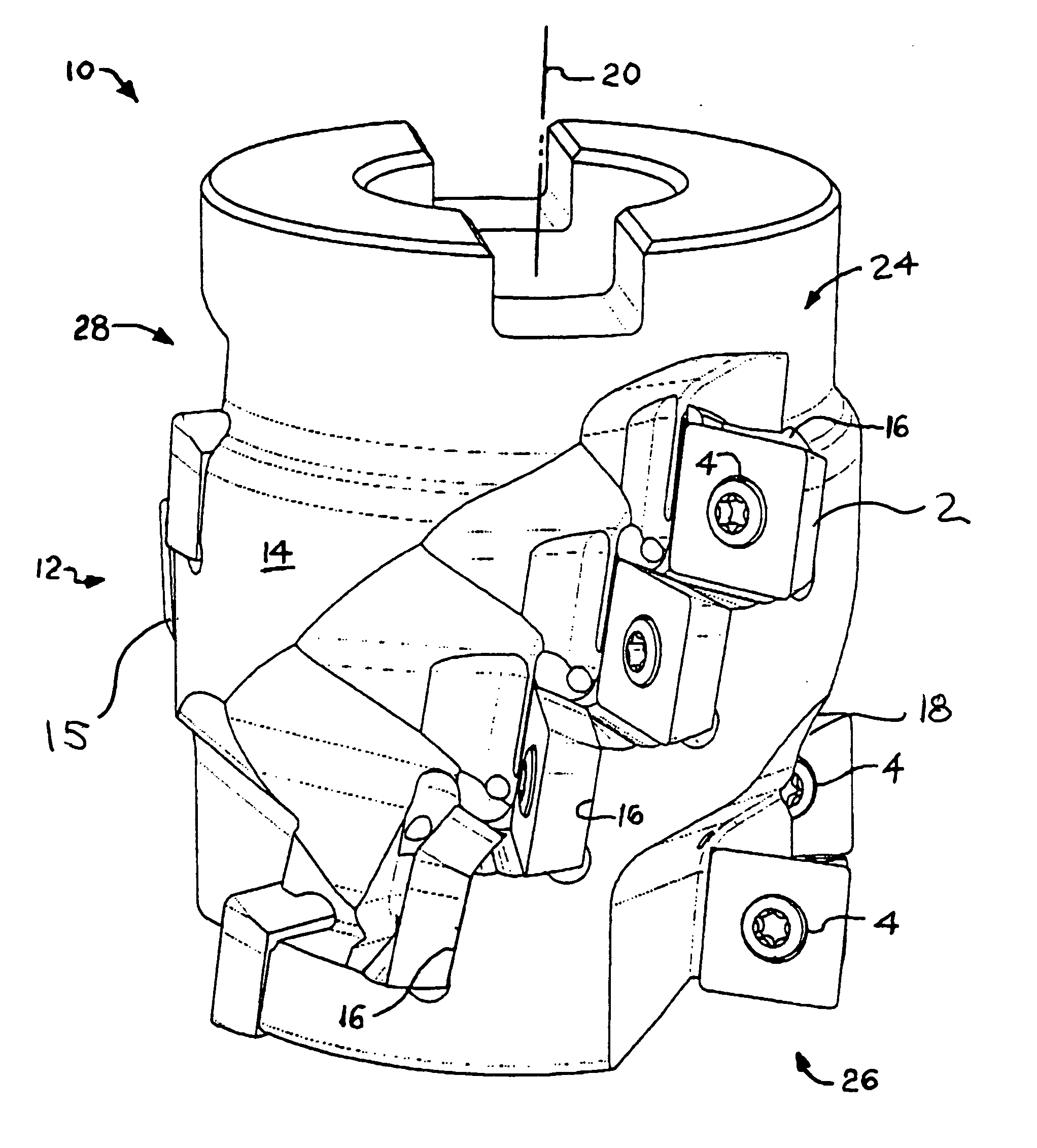
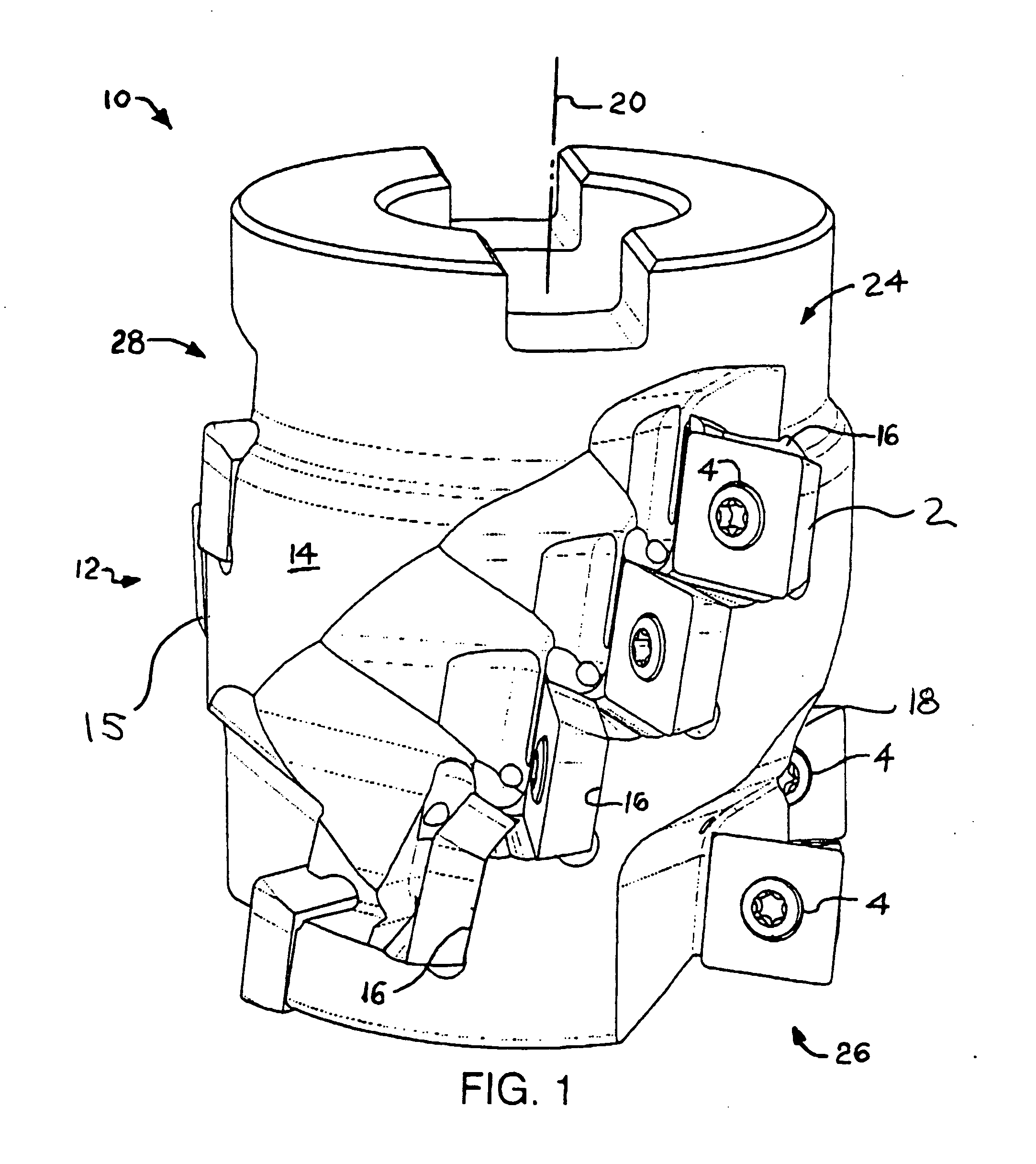
[0021] Referring to the Drawings, wherein like reference characters represent like elements throughout the various Figures, FIG. 1 shows a rotary cutting tool 10 in accordance with the present invention. Tool 10 comprises a body 12 having a circumferential face 14 bearing a plurality of pockets 16 for receiving cutting inserts 2. Circumferential face 14 is generally cylindrical and interrupted by pockets 16 and other structural features of tool 10, in the embodiment of FIG. 1. Other than their orientation on tool 10, pockets 16 are conventional, having threaded holes (not visible) for receiving screws 4 to retain inserts 2. Pockets 16 are arranged in rows, which appear horizontally arrayed when rotational axis 20 of tool 10 is vertical, as depicted in FIG. 1, and columns. Rotational axis 20 is disposed within circumferential face 14 of body 12.

[0022] Rows refer to pockets 16 which are generally at the same vertical level when tool 10 is vertically oriented as seen in FIG. 1. Pocket...


PUM


Abstract

A rotary cutting tool such as a helical end mill, having pockets arranged to overcome harmonic vibrations. The tool has at least two and in one embodiment all three of three spacing irregularities. In the first irregularity, columns of pockets, typically associated with flutes, are staggered circumferentially out of even spacing. In a preferred embodiment having three flutes, the flutes are mostly not centered on one hundred twenty degree intervals. In the second irregularity, at least some pockets are arranged at different radial rake angles. In the third irregularity, at least some pockets are arranged at different axial rake angles.

Description

BACKGROUND OF THE INVENTION [0001] 1. Field of the Invention [0002] The present invention relates to machine tools for shaping a work piece, and more particularly to rotatable tools of the type provided with cutting inserts. Orientation of inserts on the tool is varied to avoid repetitive orientation which may promote vibrational harmonics during operation. [0003] 2. Description of the Related Art [0004] Machining work pieces by rotary cutting tools may cause objectionable vibrational harmonics to occur. This results in chatter and other phenomena which may cause flaws in the machined product. It is not desirable to alter rotational speeds of a machine tool and rate of advance speeds of a cutting tool as such steps may interfere with optimal productivity. It is known to vary circumferential spacing of inserts and their pockets in a rotary cutting tool to break up harmonics which might otherwise occur. This approach is shown in U.S. Pat. No. 4,092,082, issued on May 30, 1978, to Seve...

Claims


Application Information

Patent Timeline
Patent Type & Authority Applications(United States)
IPC IPC(8): B23C5/00B23C5/10B23C5/20B26D1/12
CPCB23C5/006B23C5/109B23C2210/0407B23C2210/282Y10T407/1952Y10T407/1936Y10T407/1956Y10T407/1906B23C2250/16
Inventor LONG, THOMAS J. IICRAIG, KAREN A.DUDZINSKY, RONALD L.FILHO, RUY FROTA DE SOUZA
Owner KENNAMETAL INC
Why Eureka
Try Eureka