Magnetic actuator
a technology of magnetic actuators and actuators, which is applied in the field of magnetic actuators, can solve the problems of deterioration of response characteristics, increase in size and cost of the above-mentioned exciting power supply, etc., and achieve the effect of improving response characteristics and minimizing the occurrence of eddy currents
- Summary
- Abstract
- Description
- Claims
- Application Information
AI Technical Summary
Benefits of technology
Problems solved by technology
Method used
Image

Examples
first embodiment
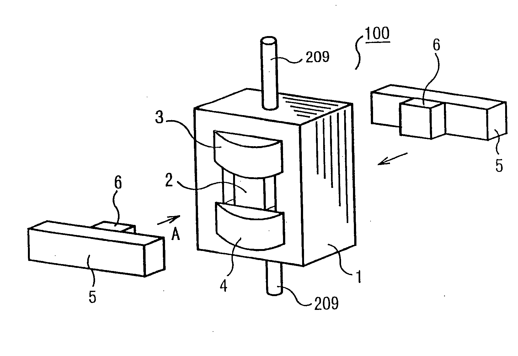
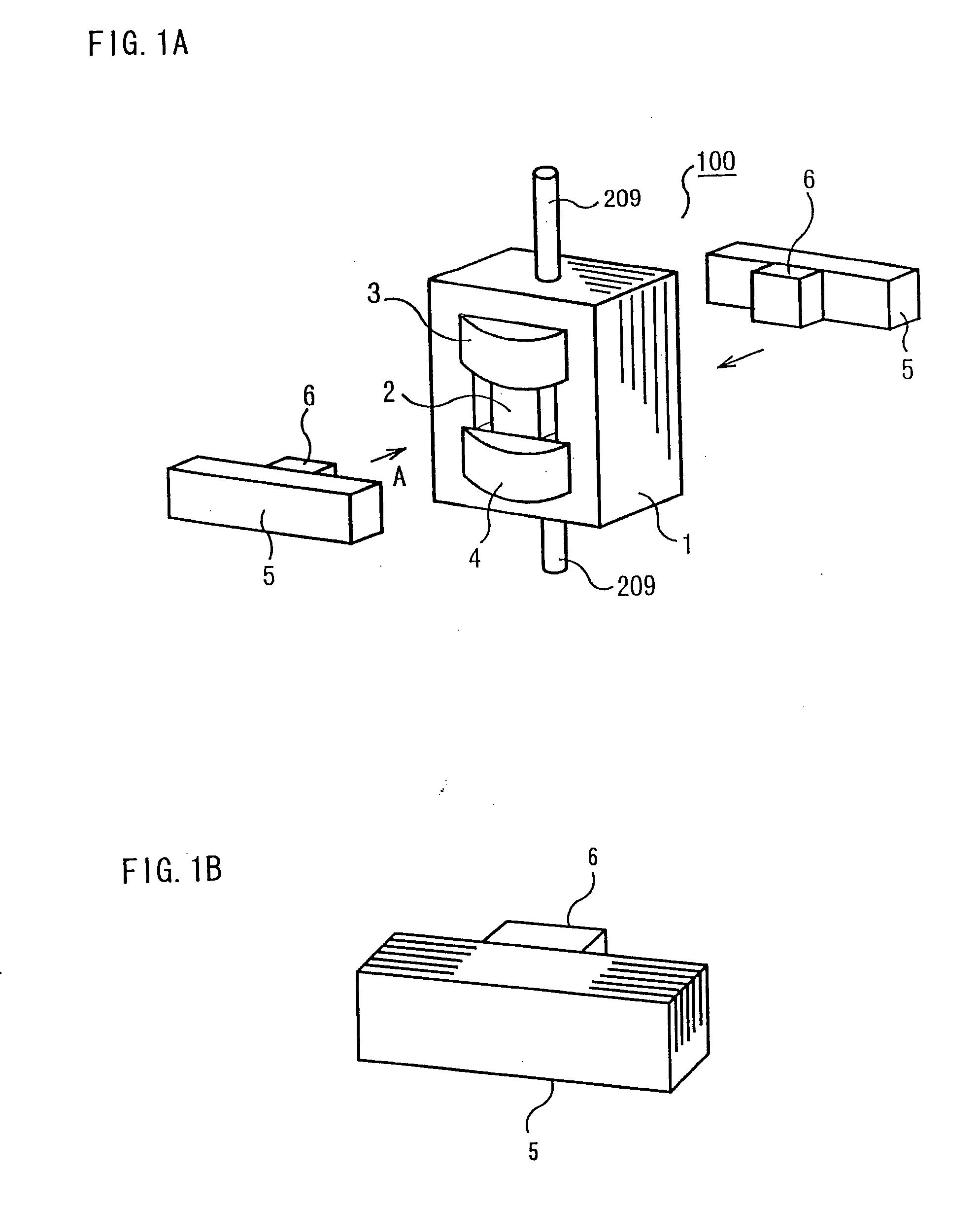
[0044] A magnetic actuator 100 according to a first embodiment of the invention is described with reference to FIGS. 1A-1B to 6A-6B and 8A-8C.
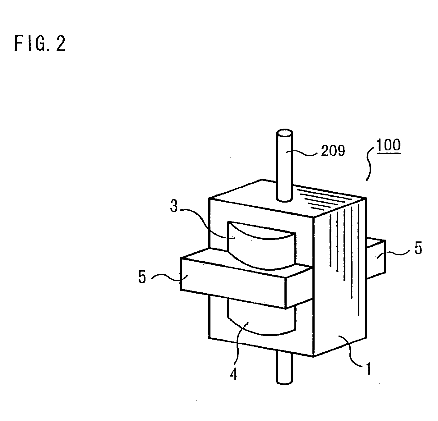
[0045]FIG. 1A-1B is a partially exploded perspective view of the magnetic actuator 100, FIG. 2 is a perspective view of the magnetic actuator 100, and FIGS. 3A-3B are sectional diagrams generally showing a yoke and armature arrangement.
[0046] Referring to these Figures, the magnetic actuator 100 includes a first yoke 1 formed of an upper yoke section 1a, a lower yoke section 1b and side yoke sections 1c, an armature 2, a first coil 3, a second coil 4, a pair of second yokes 5, a pair of permanent magnets 6 and left and right poles 7. The numerals 8 and 9 indicate first and second positions of the armature 2, respectively. Designated by the numeral 209 is a rod which passes through the upper and lower yoke sections 1a, 1b and is joined to the armature 2 at the bottom and to one of contacts 210 of a circuit breaker 200 at the top.
[0047] The f...
second embodiment
[0082] A magnetic actuator 100 according to the second embodiment of the invention is described with reference to FIGS. 5A-5B and 7A-7B.
[0083]FIG. 5A is a sectional front view of the magnetic actuator 100 and FIG. 5B is a side view of the same. The second yokes 5 are partially cut away in FIG. 5A.
[0084] Referring to FIG. 5A, the magnetic actuator 100 includes a first yoke 1 formed of an upper yoke section 1a, a lower yoke section 1b and side yoke sections 1c, an armature 2c, a first coil 3a, a second coil 4a, a pair of end plates 10a in which openings 10b are formed, a spring 12 provided between the upper yoke section 1a and the armature 2c, and a jack bolt 15 provided in one of the second yokes 5. As stated earlier with reference to the first embodiment, W1 indicates the vertical thickness of the upper yoke section 1a and W2 indicates the vertical thickness of the lower yoke section 1b.
[0085] As previously mentioned, the force needed for holding the contacts 210 of the circuit b...
third embodiment
[0090] Although each of the second yokes 5 is shaped in an elongate parallelepipedic form in the aforementioned first and second embodiments, a magnetic actuator 100 according to the third embodiment discussed below employs E-shaped second yokes 5a each having three inward projecting portions as shown in FIG. 9. A permanent magnet 6a is attached to the central projecting portion of each second yoke 5a as illustrated. When assembled into the magnetic actuator 100, the permanent magnets 6a on the individual second yokes 5a are positioned face to face with the armature 2 with air gaps g created in between.
[0091] The two second yokes 5a are affixed to the side yoke sections 1c of the first yoke 1 by bolts or fastening parts which are not illustrated. The second yokes 5a may be made of solid steel plates or laminations of thin magnetic steel or thin steel sheets.
[0092] Alternatively, two permanent magnets 6a may be affixed to far ends of the outer projecting portions of each second yok...
PUM
| Property | Measurement | Unit |
|---|---|---|
| area | aaaaa | aaaaa |
| magnetomotive force | aaaaa | aaaaa |
| magnetic | aaaaa | aaaaa |
Abstract
Description
Claims
Application Information
 - Generate Ideas
- Intellectual Property
- Life Sciences
- Materials
- Tech Scout
- Unparalleled Data Quality
- Higher Quality Content
- 60% Fewer Hallucinations
Browse by: Latest US Patents, China's latest patents, Technical Efficacy Thesaurus, Application Domain, Technology Topic, Popular Technical Reports.
© 2025 PatSnap. All rights reserved.Legal|Privacy policy|Modern Slavery Act Transparency Statement|Sitemap|About US| Contact US: help@patsnap.com