Zoom lens system

a zoom lens and zoom lens technology, applied in the field of zoom lens system, can solve the problems of inability to achieve further miniaturization of the camera body, i.e., obtaining a thin camera body, and increasing the thickness of the camera when the zoom lens barrel (zoom lens system) is fully retracted, etc., and achieves the effect of higher zoom ratio

Inactive Publication Date: 2005-04-28
ASAHI KOGAKU KOGYO KK
View PDF15 Cites 4 Cited by
  • Summary
  • Abstract
  • Description
  • Claims
  • Application Information

AI Technical Summary

Benefits of technology

[0015] The present invention achieves a higher zoom ratio and further miniaturization in a zoom lens system of the four-lens-group arrangement, i.e., a positive lens group, a negative lens group, a positive lens group, and a negative lens group, in this order from the object.

Problems solved by technology

Consequently, the total thickness of all the lens groups inevitably increases; thereby, the thickness of the camera when the zoom lens barrel (zoom lens system) is fully retracted is increased, and further miniaturization of the camera body, i.e., obtaining a thin camera body, cannot be achieved.
However, the zoom lens systems disclosed in these publications do not sufficiently attain a higher zoom ratio and further miniaturization of a zoom lens system.

Method used


Image

  • Zoom lens system
  • Zoom lens system
  • Zoom lens system

Examples


embodiment 1

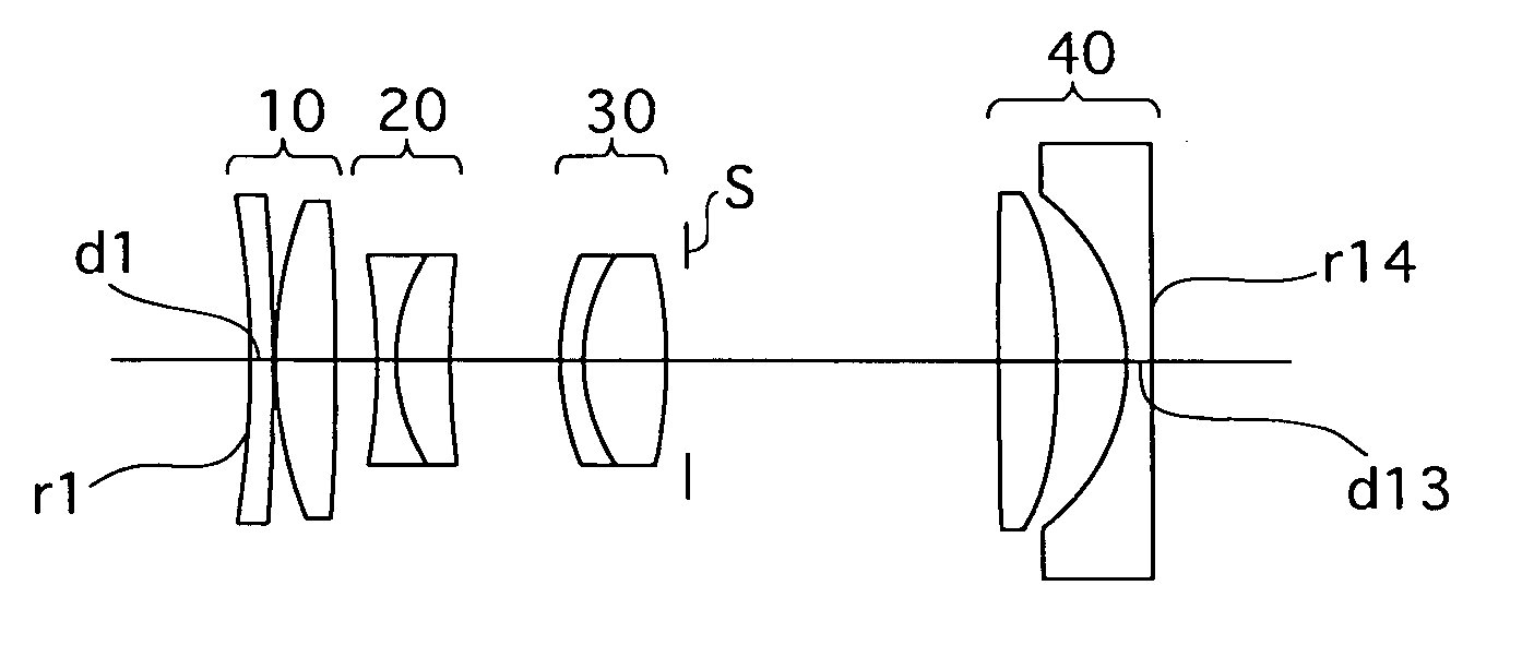
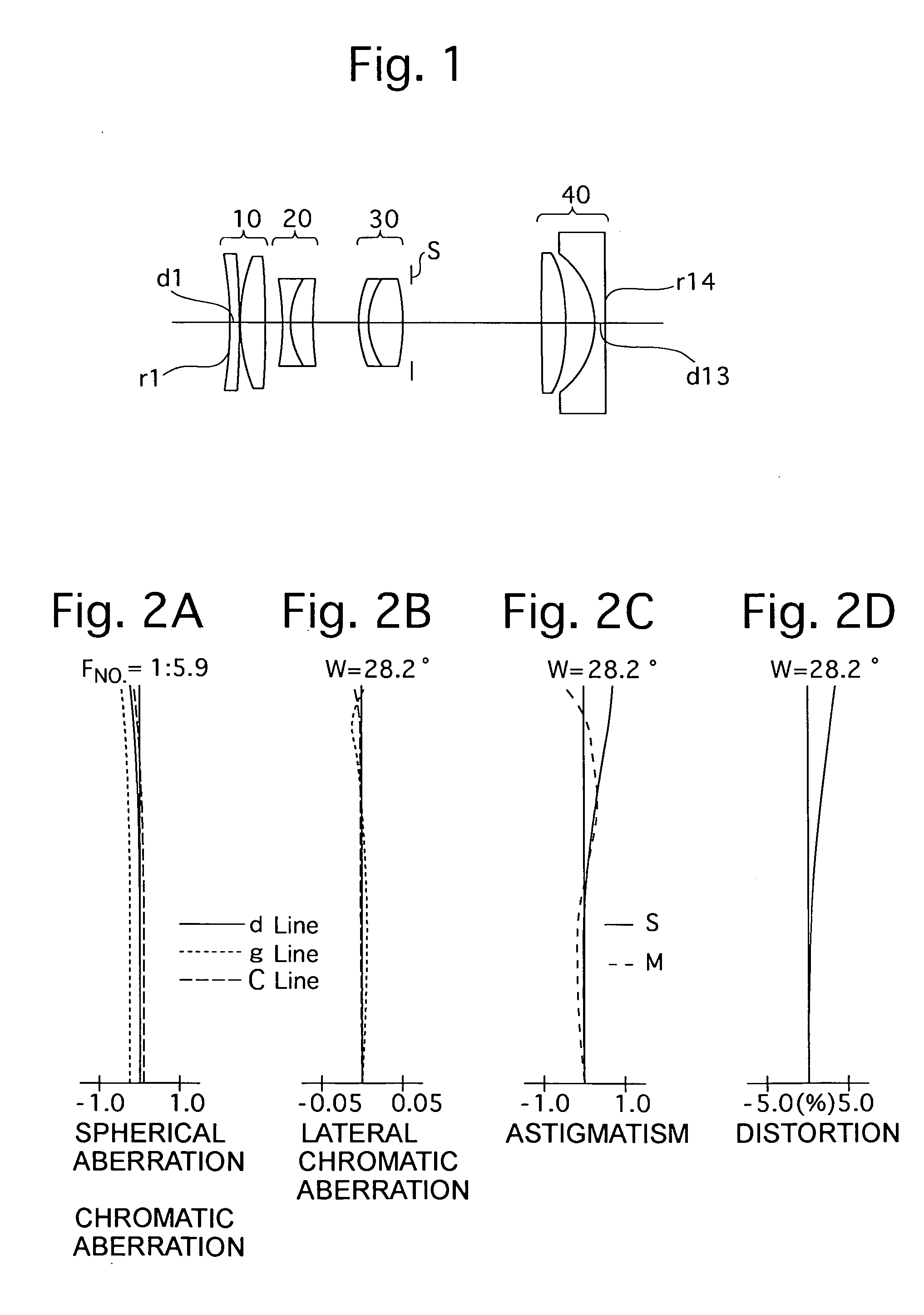
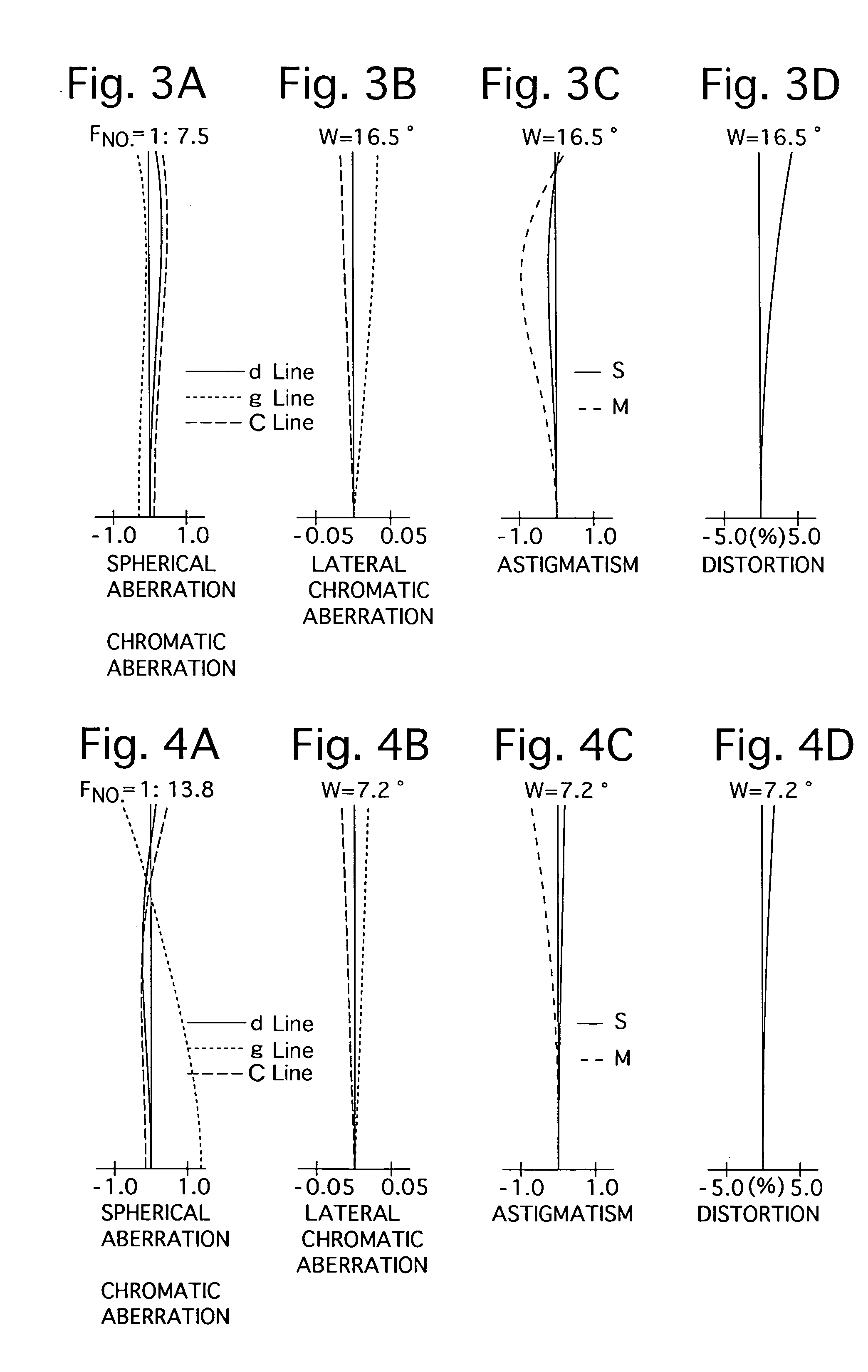
[0118]FIG. 1 is the lens arrangement of the zoom lens system according to the first embodiment of the present invention. The first embodiment corresponds to the lens-group moving paths shown in FIG. 16. FIGS. 2A through 2D show aberrations occurred, at the short focal length extremity (fw), in the lens arrangement shown in FIG. 1. FIG. 3A through 3D show aberrations occurred, at an intermediate focal length (fm), in the lens arrangement shown in FIG. 1. FIGS. 4A through 4D show aberrations occurred, at the long focal length extremity (ft), in the lens arrangement shown in FIG. 1. Table 1 shows the numerical data of the first embodiment.

[0119] Surface Nos. 1 through 4 constitute the positive first lens group 10, surface Nos. 5 through 7 constitute the negative second lens group 20, surface Nos. 8 through 10 constitute the positive third lens group 30, and surface Nos. 11 through 14 constitute the negative fourth lens group 40.

[0120] The diaphragm S is provided 1.0 mm behind (on the...

embodiment 2

[0125]FIG. 5 is the lens arrangement of the zoom lens system according to the second embodiment of the present invention. The second embodiment corresponds to the lens-group moving paths shown in FIG. 16. FIGS. 6A through 6D show aberrations occurred, at the short focal length extremity (fw), in the lens arrangement shown in FIG. 5. FIG. 7A through 7D show aberrations occurred, at an intermediate focal length (fm), in the lens arrangement shown in FIG. 5. FIGS. 8A through 8D show aberrations occurred, at the long focal length extremity (ft), in the lens arrangement shown in FIG. 5. Table 2 shows the numerical data of the second embodiment. The basic lens arrangement of the second embodiment is the same as that of the first embodiment. The diaphragm S is provided 1.16 mm behind (on the image plane side) the third lens group 30 (surface No. 10).

TABLE 2FNO = 1:5.9-7.6-13.8f = 39.00-70.00-168.00W = 28.2-16.6-7.2fB = 9.42-23.37-63.72Surface No.rdNdν 1*−35.6931.101.8466623.8 2−76.1430.1...

embodiment 3

[0126]FIG. 9 is the lens arrangement, at the short focal length extremity (fw), of the zoom lens system according to the third embodiment of the present invention. The third embodiment corresponds to the lens-group moving paths shown in FIG. 15. FIGS. 10A through 10D show aberrations occurred in the lens arrangement shown in FIG. 9. FIG. 11A through 11D show aberrations occurred in the lens arrangement shown in FIG. 9 at the first intermediate focal length (fm) (before switching). FIGS. 12A through 12D show aberrations occurred in the lens arrangement shown in FIG. 9 at the second intermediate focal length (fm′) (after switching). FIG. 13 is the lens arrangement, at the long focal length extremity (ft), of the zoom lens system according to the third embodiment of the present invention. FIGS. 14A through 14D show aberrations occurred in the lens arrangement shown in FIG. 13. Table 3 shows the numerical data of the third embodiment.

[0127] The values of f, W and fB are each shown in t...


PUM


Abstract

A zoom lens system includes a first lens group, a second lens group, a third lens group and a fourth lens group. Zooming is performed by moving each lens group in the optical axis direction. The zoom lens system satisfies the following conditions:
0.35<log(fT23/fW23)/log(ft/fw)<0.55   (1);
0.4<(LDW−LDT)/(ft/fw)<0.7   (2);
wherein
    • [0001]
    • f23W: the combined focal length of the second and the third lens groups at the short focal length extremity;
    • [0002]
    • f23T: the combined focal length of the second and the third lens groups at the long focal length extremity;
    • [0003]
    • ft: the focal length of the entire zoom lens system at the long focal length extremity;
    • [0004]
    • fw: the focal length of the entire zoom lens system at the short focal length extremity;
    • [0005]
    • LDw: the distance from the most object-side surface of the first lens group to the most image-side surface of the fourth lens group at the short focal length extremity; and
    • [0006]
    • LDT: the distance from the most object-side surface of the first lens group to the most image-side surface of the fourth lens group at the long focal length extremity.

Description

BACKGROUND OF THE INVENTION [0007] 1. Field of the Invention [0008] The present invention relates to a zoom lens system which is used in a photographing camera such as a lens shutter camera. [0009] 2. Description of the Prior Art [0010] A zoom lens system of a compact camera does not require a long back focal distance, unlike a zoom lens system of a single lens reflex (SLR) camera which requires a space to provide a mirror behind the photographing lens system. [0011] As a zoom lens system of a compact camera in which there is no need to consider a back focal distance, a zoom lens system of three-lens-group arrangement, e.g., a first lens group having a positive refractive power, a second lens group having a positive refractive power, and a third lens group having a negative refractive power, in this order from the object, has been often employed in the case of a zoom lens system with a zoom ratio of more than 3, as shown in Japanese Unexamined Patent Publication (hereinafter, JUPP) ...

Claims


Application Information

Patent Timeline
Patent Type & Authority Applications(United States)
IPC IPC(8): G02B15/20G02B13/18G02B15/173
CPCG02B15/173G02B15/144105
Inventor ENOMOTO, TAKASHI
Owner ASAHI KOGAKU KOGYO KK
Why Eureka
Try Eureka