Method and apparatus for depositing glass soot
a glass soot and glass technology, applied in the field of glass soot depositing methods and equipment, can solve the problems of increasing the attenuation of optical fibers operating at wavelengths, reducing the attenuation performance of optical fibers, and affecting the operation of optical fibers
- Summary
- Abstract
- Description
- Claims
- Application Information
AI Technical Summary
Benefits of technology
Problems solved by technology
Method used
Image
Examples
example 1
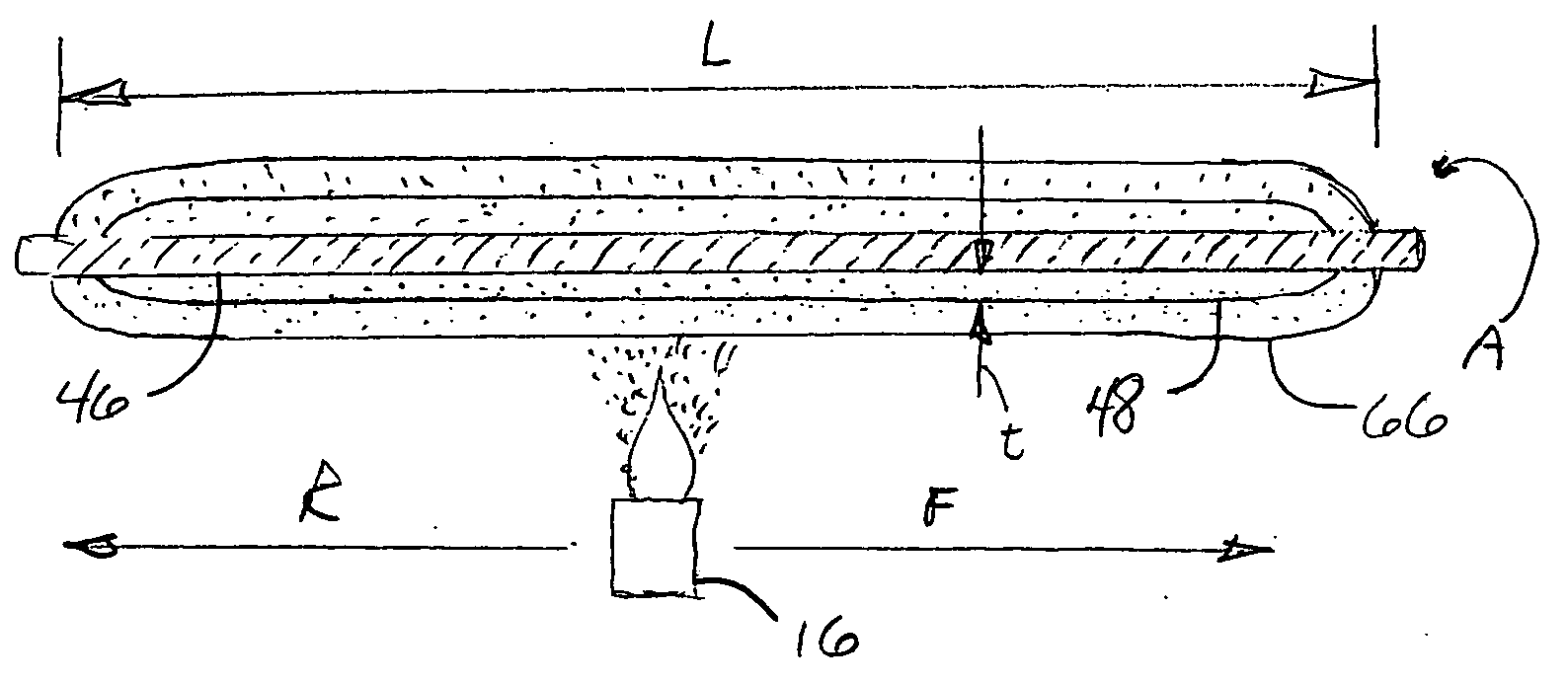
[0066]FIG. 12 shows the calculated effect on surface temperature of a single burner traversing adjacent to and parallel with the longitudinal axis of a glass rod during the deposition of glass soot onto the rod. The data show temperature vs. time for the first few forward traverses of the burner flame. The forward traverse rate of the burner was evaluated for three traversing conditions; 30 seconds / pass, shown by curve 122, 60 seconds / pass, shown by curve 124, and 120 seconds / pass as indicated by curve 126. The time required for a pass is interpreted as the time between the burner flame passing a given point on the glass rod during one forward traverse to the time the flame passed the same point during the next forward traverse. The figure shows that the calculated peak temperature varies from between about 550° C. to 640° C. for the 30 second / pass rate, between about 660° C. and 780° C. for the 60 second / pass rate and between about 890° C. and 960° C. for the 120 seconds / pass rate....
example 2
[0067]FIG. 14 depicts the temperature envelope as a function of time during a deposition of glass soot for two rods, a first glass rod having a diameter of about 1.6 cm, as indicated by curve 134, and a second glass rod having a diameter of about 3.2 cm as indicated by dashed curve 136. (As noted above, the temperature envelope encompasses and defines the maximum and minimum temperatures during each pass of a traversing burner or burners during the deposition process.) The same mass of soot was deposited onto each glass rod. The final diameter of the first glass rod was about 4 cm, and the final diameter of the second glass rod was about 4.866 cm. During the deposition of soot, the temperature of the deposition surface of each soot preform was monitored by optical pyrometer. FIG. 14 shows that a glass rod having a large diameter has a lower peak surface temperature for each pass of the burner, and therefore a lower overall temperature envelope, than a glass rod having a smaller diam...
example 3
[0069]FIG. 16 shows a comparison between deposition with a single-burner and deposition using two burners. Both burner arrangements of FIG. 16 had a traverse cycle of 60 seconds / traverse. According to FIG. 16, the single burner data 142 displayed a maximum calculated temperature of about 800° C., while the two-burner data 144 had a maximum calculated temperature of about 1000° C. FIG. 17 depicts the overall temperature envelope as a function of time for the single burner case compared with a two burner configuration throughout a deposition process (i.e. many thousands of passes). The overall temperature envelope 148 of the two-burner configuration has a higher maximum temperature than the envelope 146 for a single burner configuration. Therefore, the use of two burners to deposit soot would be expected to produce a higher attenuation due to the adsorption of water than the use of a single burner. The figure shows an increased temperature for the use of two burners. FIG. 17 also indi...
PUM
| Property | Measurement | Unit |
|---|---|---|
| Thickness | aaaaa | aaaaa |
| Thickness | aaaaa | aaaaa |
| Diameter | aaaaa | aaaaa |
Abstract
Description
Claims
Application Information
 - R&D
- Intellectual Property
- Life Sciences
- Materials
- Tech Scout
- Unparalleled Data Quality
- Higher Quality Content
- 60% Fewer Hallucinations
Browse by: Latest US Patents, China's latest patents, Technical Efficacy Thesaurus, Application Domain, Technology Topic, Popular Technical Reports.
© 2025 PatSnap. All rights reserved.Legal|Privacy policy|Modern Slavery Act Transparency Statement|Sitemap|About US| Contact US: help@patsnap.com


