
Wall mounted-type microwave oven

Inactive Publication Date: 2005-05-05
SAMSUNG ELECTRONICS CO LTD
View PDF3 Cites 0 Cited by
  • Summary
  • Abstract
  • Description
  • Claims
  • Application Information

AI Technical Summary

Benefits of technology

[0010] Accordingly, it is an aspect of the present invention to provide a wall mounted-type microwave oven provided with a hood having an inlet port with an improved structure, thus effectively drawing exhaust gases and food odors produced from a plurality of gas burners placed below the hood.

Problems solved by technology

Therefore, exhaust gases produced from gas burners placed near the exhaust passage are smoothly drawn into the exhaust passage, whereas exhaust gases produced from gas burners placed far from the exhaust passage are not smoothly drawn into the exhaust passage.
Therefore, the conventional wall mounted-type microwave oven presents a problem because the wall mounted-type microwave oven does not effectively draw and discharge exhaust gases produced from all gas burners placed below the hood.

Method used


Image

  • Wall mounted-type microwave oven
  • Wall mounted-type microwave oven
  • Wall mounted-type microwave oven

Examples


first embodiment

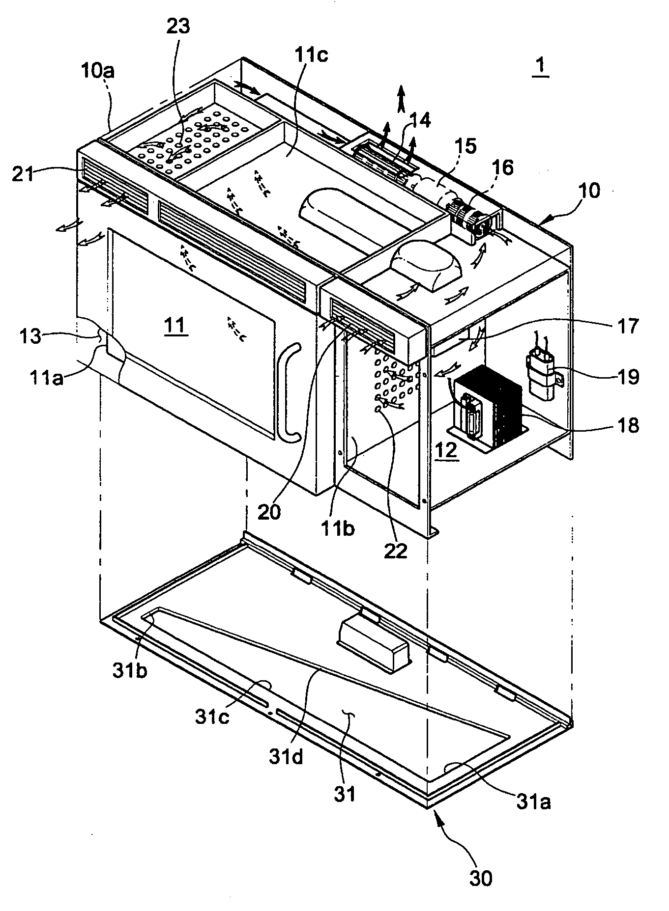
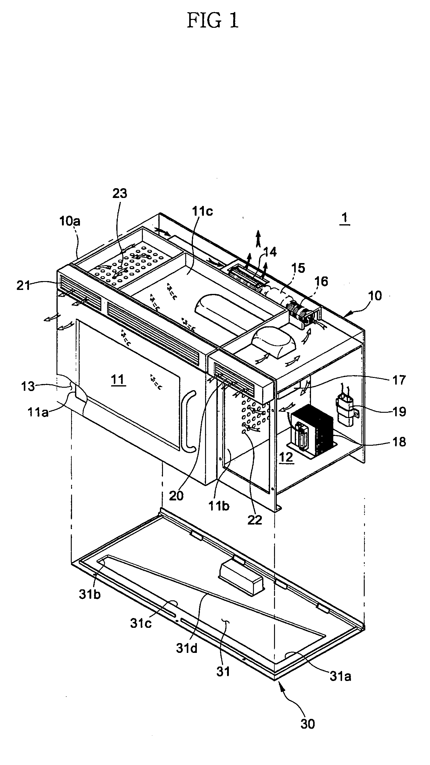
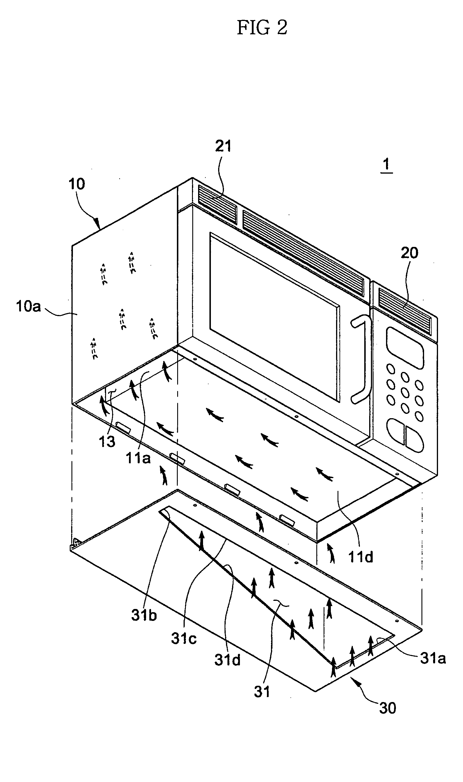
[0024]FIGS. 1 and 2 respectively show an exploded front perspective view and an exploded bottom perspective view of a wall mounted-type microwave oven having a hood according to the present invention.

[0025] As shown in FIGS. 1 and 2, the wall mounted-type microwave oven 1 includes a cabinet 10, which is box-shaped, and defines an external appearance of the wall mounted-typed microwave oven 1. The cabinet 10 is partitioned into a cooking cavity 11 and a machine room 12.

[0026] An exhaust passage 13 is provided between a left side plate 10a of the cabinet 10 and a left side plate 11 a of the cooking cavity 11. The exhaust passage 13 guides exhaust gases and fumes produced from a cooking apparatus 50 (shown in FIG. 5) located below the cabinet 10 that includes gas burners 51 and 52to discharge the exhaust gases and the fumes to an outside of the wall mounted-type microwave oven. Further, an exhaust fan 14 and a fan motor 15 are installed to an upper rear portion of the cabinet 10 to di...

second embodiment

[0036]FIGS. 3 and 4 respectively show an exploded front perspective view and an exploded bottom perspective view of a wall mounted-type microwave oven having a hood, according to the present invention.

[0037] As shown in FIGS. 3 and 4, the wall mounted-type microwave oven 1 according to the second embodiment includes the cabinet 10 with the hood 30a mounted to the bottom portion of the cabinet 10. First and second inlet ports 32 and 33, which have the same shape as the inlet port 31 of the wall mounted-type microwave oven 1 of the first embodiment, are provided on right and left sides of the hood 30a, respectively. Accordingly, the general construction of the wall mounted-type microwave oven 1 according to the second embodiment remains the same as the wall mounted-type microwave oven 1 according to the first embodiment, with the exception of a plurality of inlet ports 32 and 33 provided in the hood 30a.

[0038] According to an aspect of the present invention, the first and second inle...


PUM


Abstract

A wall mounted-type microwave oven provided with a hood having an inlet port with an improved structure, thus effectively drawing exhaust gases and food odors produced from a plurality of gas burners placed below the hood. The wall mounted-type microwave oven includes a cabinet and a hood. The cabinet has, at predetermined portions thereof, an exhaust passage and an exhaust fan. The hood is mounted to a bottom portion of the cabinet, and has an inlet port to communicate with the exhaust passage. The inlet port is formed so that a width of an end of the inlet port near to the exhaust passage is less than a width of an end of the inlet port farther from the exhaust passage. Thus, the inlet port is formed so that an area of a portion of the inlet port on which a weaker suction force of the exhaust fan acts is larger than an area of a portion of the inlet port on which a stronger suction force of the exhaust fan acts.

Description

CROSS-REFERENCE TO RELATED APPLICATIONS [0001] This application claims the benefit of Korean Patent Application No. 2003-77701, filed Nov. 4, 2003 in the Korean Intellectual Property Office, the disclosure of which is incorporated herein by reference. BACKGROUND OF THE INVENTION [0002] 1. Field of the Invention [0003] The present invention relates to wall mounted-type microwave ovens, and more particularly, to a wall mounted-type microwave oven provided with a hood having an inlet port with an improved structure, thus effectively drawing exhaust gases and food odors produced from a plurality of gas burners placed below the hood. [0004] 2. Description of the Related Art [0005] Generally, a wall mounted-type microwave oven is mounted to a wall of a kitchen above a plurality of gas burners. The wall mounted-type microwave oven collaterally serves to exhaust gases, fumes, and food odors produced from the gas burners, which are positioned under the microwave oven, in addition to cooking ...

Claims


Application Information

Patent Timeline
IPC IPC(8): F24C7/02F24C15/20H05B6/80
CPCF24C15/2042H05B6/6429H05B6/6423F24C15/20
Inventor KANG, JEON-HONG
Owner SAMSUNG ELECTRONICS CO LTD
Learn More