Clamping device

US20050093252A1Inactive Publication Date: 2005-05-05GMCA PTY LIMITED

Image

  • Clamping device
  • Clamping device
  • Clamping device

Examples


Embodiment Construction

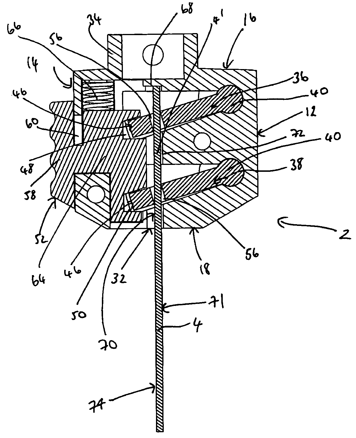
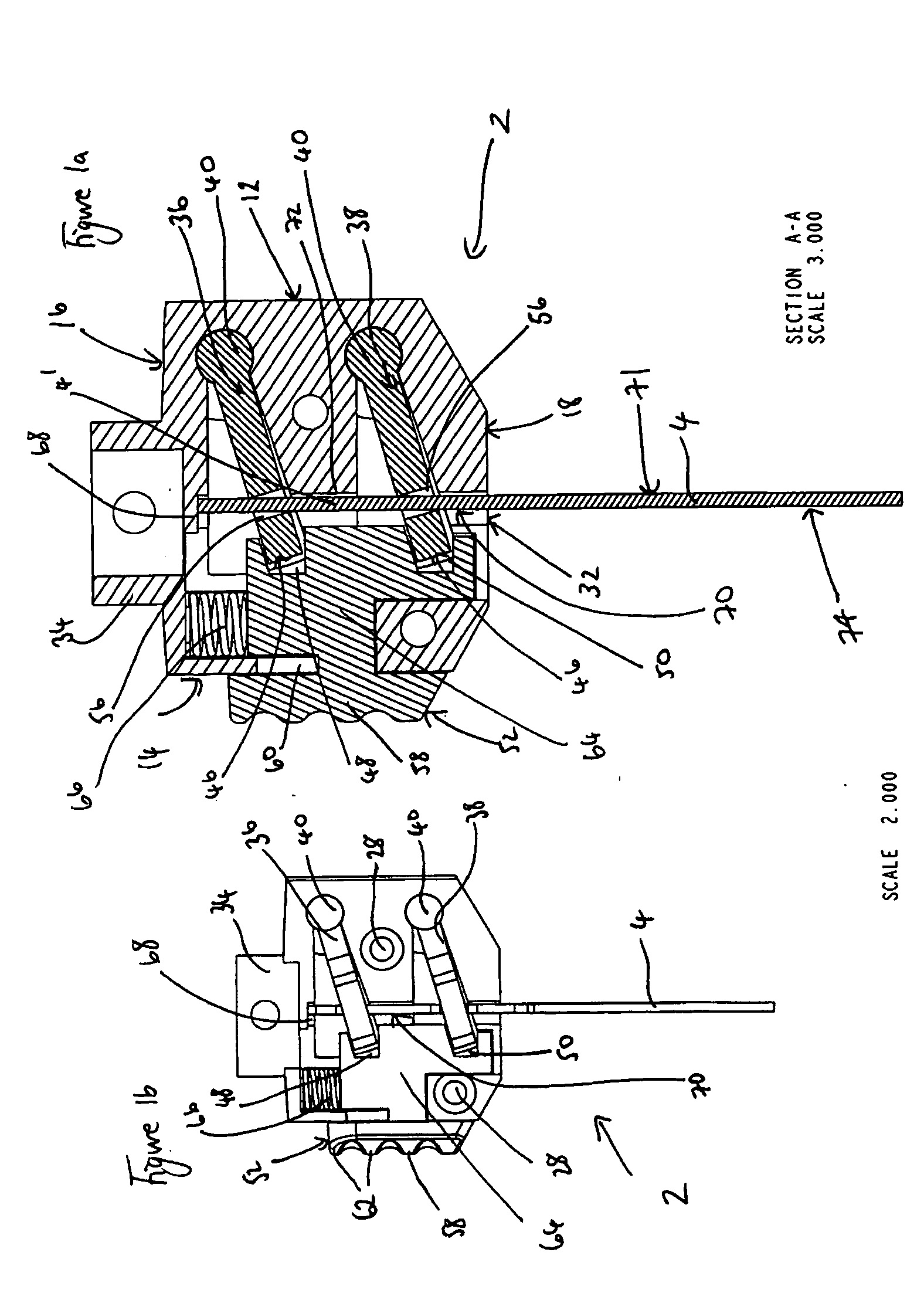
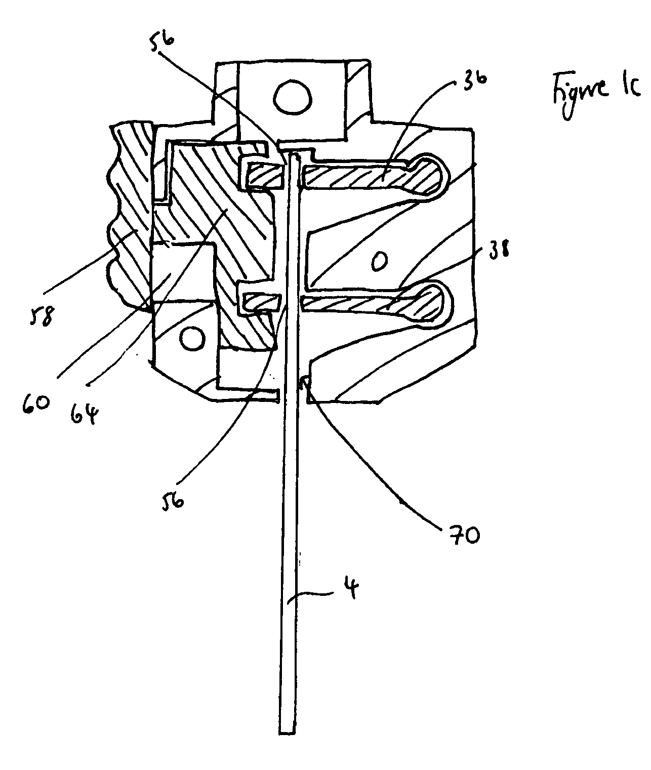
[0015] According to a first aspect of the present invention there is provided a clamping device for a tool component, said clamping device including a housing with a tool component location channel defined therein for the location of at least a part of a tool component in use, said clamping device further including one or more clamping members movably mounted in said housing, characterised in that said clamping members are capable of moving between a locked position, wherein the tool component can be clamped between one or more surfaces of said clamping members and one or more walls defining the tool component location channel, and an unlocked position, wherein the tool component can be inserted and / or removed from the clamping device.

[0016] Preferably user actuation means are provided to move said clamping members between said locked and unlocked positions. At least part of the user actuation means is accessible from the exterior of the device housing.

[0017] Preferably the user a...


PUM

PropertyMeasurementUnit
Distanceaaaaaaaaaa
Surface areaaaaaaaaaaa
Resilienceaaaaaaaaaa

Abstract

A clamping device is provided for a tool component, such as a saw blade. The clamping device includes a housing with a saw blade location channel defined therein for the location of at least a part of the saw blade in use. Clamping members are movably mounted in the housing and can be moved between a locked position, wherein the saw blade is clamped between one or more surfaces of said clamping members and one or more walls defining the saw blade location channel, and an unlocked position, wherein the saw blade can be inserted or removed from the clamping device.

Description

BACKGROUND OF THE INVENTION [0001] This invention relates to a clamping device for use with a tool component for allowing releasable clamping of said tool component with respect to a tool. [0002] Although the following description refers almost exclusively to a clamping device for use with a saw blade of a power tool, it will be appreciated by persons skilled in the art that the clamping device of the present invention could be used with any tool component for use with any manual or powered tool. [0003] Tools, such as jigsaws, power saws or reciprocating saws, are typically provided with releasable blade clamping means for allowing saw blades to be replaced, removed and / or repaired as and when required. There are many different types of blade clamping means available and one example is disclosed in EP0587498 wherein a support is provided on a slideway which defines an engagement passage for a tail end of a saw blade. A retractable locking member is secured to the support and interac...

Claims


Application Information

Patent Timeline
05 May 2005
Publication
US20050093252A1
IPC
B23D51/10
CPC
Y10T279/17811; B23D51/10
Inventors
PARK, KEITH