Gas bag module

a gas bag and module technology, applied in transportation and packaging, pedestrian/occupant safety arrangements, vehicle safety arrangements, etc., to achieve the effect of reliable gas bag deployment and rapid opening of outlet openings

Inactive Publication Date: 2005-05-05
TRW AUTOMOTIVE SAFETY SYST
View PDF22 Cites 11 Cited by
  • Summary
  • Abstract
  • Description
  • Claims
  • Application Information

AI Technical Summary

Benefits of technology

[0006] It is an object of the invention to provide a gas bag module which ensures a rapid freeing of the outlet opening and a reliable deployment of the gas bag.
[0008] In a preferred embodiment of the invention, relative rotation between the diffusor elements is prevented in that a portion of one of the diffusor elements engages through an outflow opening provided on the other one of the diffusor elements.
[0010] In a further preferred embodiment, the diffusor elements have structures mutually engaging each other in a plane perpendicular to the axial direction, preventing a relative movement of the two diffusor elements. In this case, the rotation is prevented by a peripheral geometry deviating from the circular shape in a plane perpendicular to the axial direction or to the displacement path.
[0018] Alternatively, it is possible to lift the entire covering cap upon deployment of the gas bag. Here, also, a ring-shaped outlet opening is freed for the gas bag, which is formed for example by a gap opened between an edge of the covering cap and a module housing. The advantage here is that hinges or nominal fracture sites can be dispensed with in the region of the front side of the covering cap which is visible from the exterior.
[0019] Preferably, a portion of a generator carrier and / or an edge of an inflation opening of the gas bag is clamped between a ring formed on the first diffusor element and the module housing. In this way, a separate gas bag holding element can be dispensed with, because a section of the first diffusor element undertakes this task.

Problems solved by technology

As in other conventional gas bag modules the problem of reliably freeing the outlet opening for the gas bag in the shortest period of time possible on activation of the gas bag module.

Method used


Image

  • Gas bag module
  • Gas bag module
  • Gas bag module

Examples


Embodiment Construction

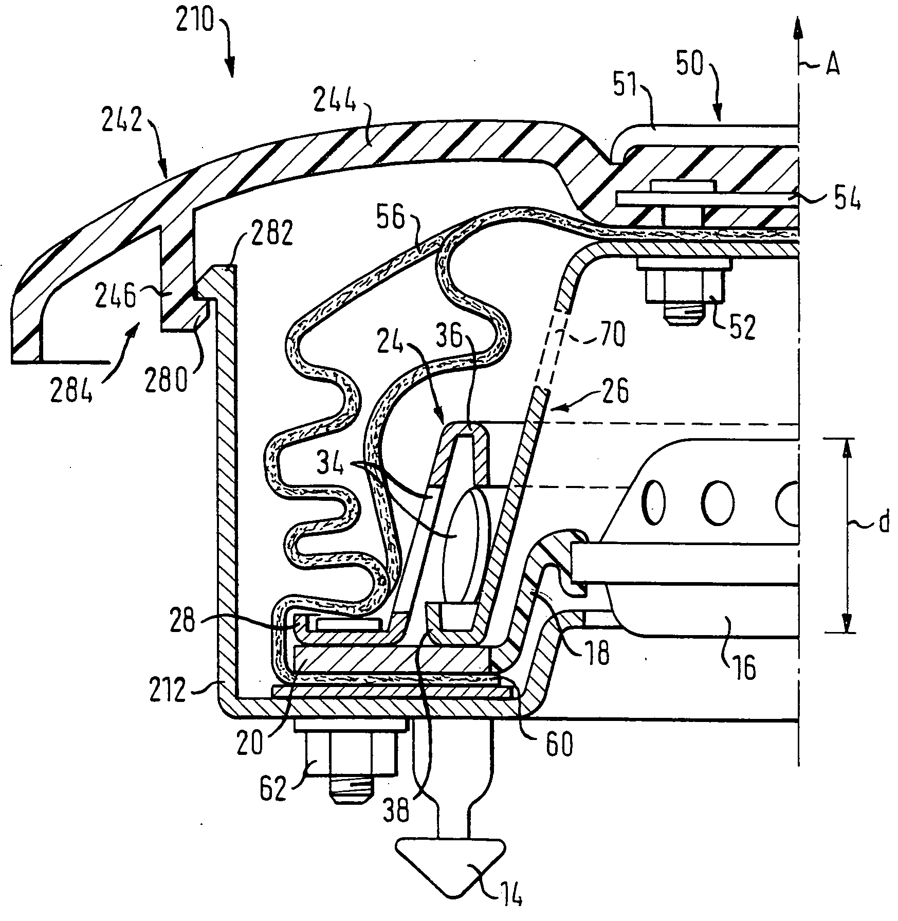
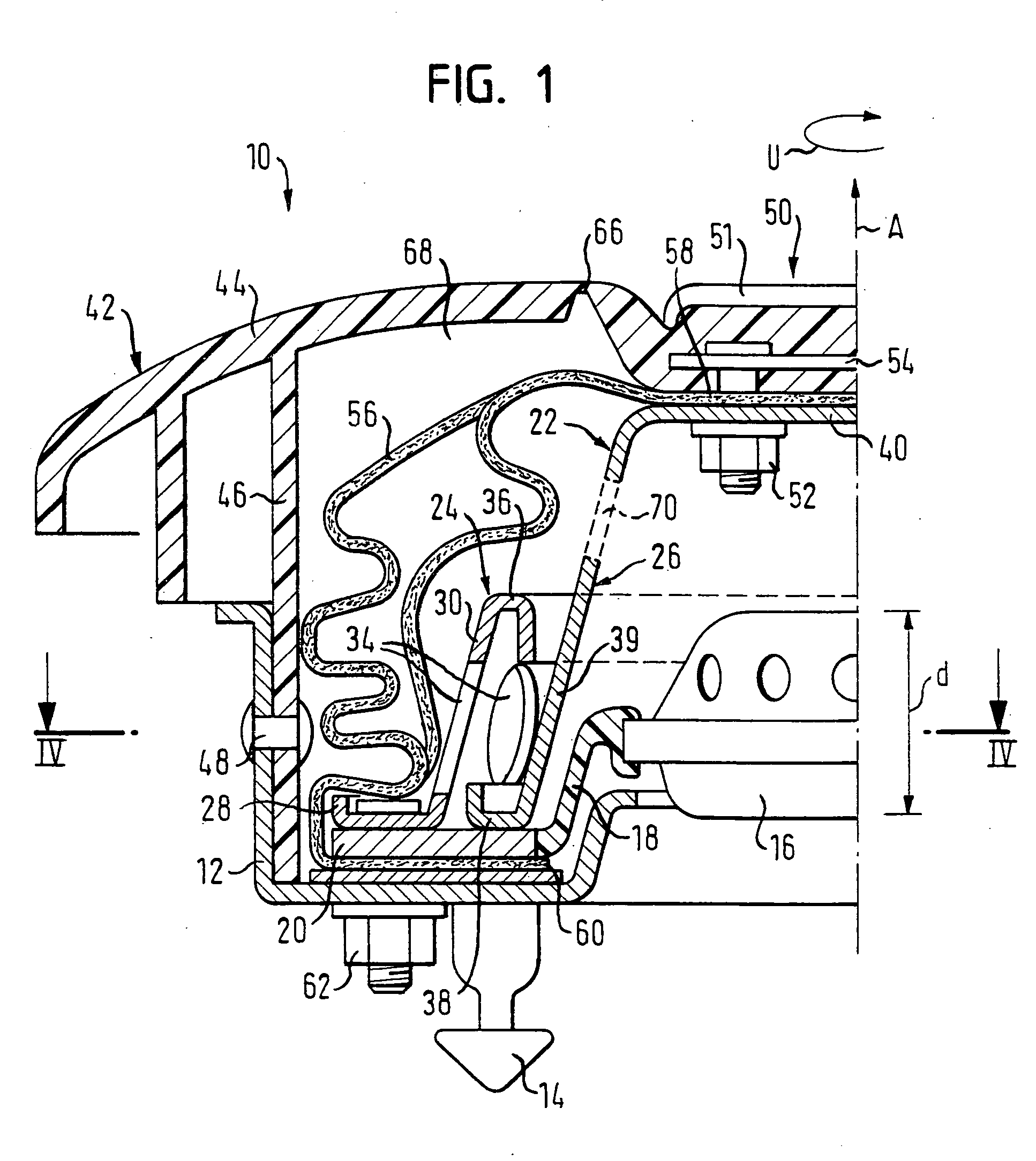
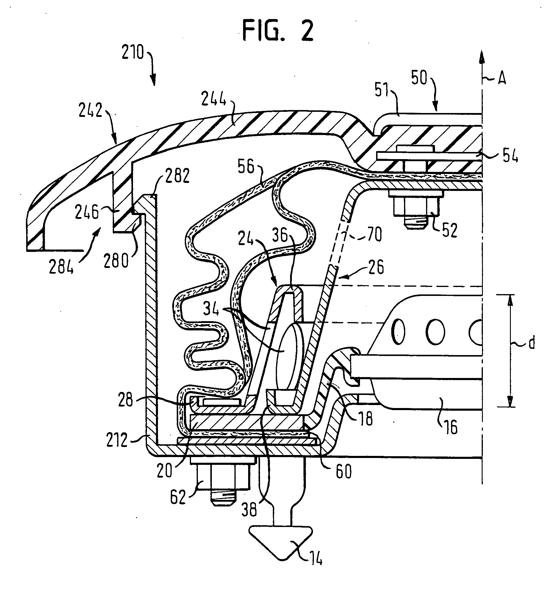
[0028] The gas bag module 10 shown in FIG. 1 contains a module housing 12, on the base of which detent elements 14 are provided for fastening the gas bag module 10 in a steering wheel. In the module housing 12 a gas generator 16 is held, mounted so as to be capable of oscillating. The gas generator 16 is connected with a flat ring-shaped flange 20 by means of an elastic ring-shaped element 18. The flange 20 here fulfils the task of a generator carrier.

[0029] The gas generator 16 is arranged below a two-part diffusor 22, which has a first diffusor element 24, fixed to the module, and a second diffusor element 26 displaceable with respect to the first diffusor element 24 by a predetermined displacement path d parallel to an axial direction A of the gas bag module 10.

[0030] The first diffusor element 24, positioned radially on the exterior, has at its base, which is directed radially outward, a ring 28 which rests on the flange 20. The ring 28 connects the flange 20 and also an edge ...


PUM


Abstract

A gas bag module (10) includes a gas bag (56) having a front wall, a center section (58) of the front wall being fastened to the gas bag module (10) and being prevented from a free movement on an unfolding of the gas bag (56). The gas bag module (10) further includes a diffusor (22) having a first diffusor element (24) fixed to the module, and a second diffusor element (26) displaceable with respect to the first diffusor element (24) by a predetermined limited displacement path (d) in an axial direction (A). The gas bag module further comprises a gas generator (16) arranged below the diffusor (22) and a covering cap (42) having a central section (50) which is fastened by at least one fastening means to the second diffusor element (26; 326; 326′). The diffusor elements (24, 26) are constructed so that the second diffusor element (26) is not displaceable in a peripheral direction (U) relative to the first diffusor element (24).

Description

TECHNICAL FIELD [0001] The invention relates to a gas bag module, in particular to a gas bag module comprising a gas bag having a front wall, a center section of the front wall being fastened to the gas bag module and being prevented from a free movement upon deployment of the gas bag. BACKGROUND OF THE INVENTION [0002] The gas bags of such gas bag modules, which are preferably employed in steering wheels, unfold in a ring shape around a substantially stationary central part of the gas bag module. The inner opening of the ring is closed by suitable means which are known to the artisan, such that in the inflated state of the gas bag no part of a vehicle occupant's body can unintentionally penetrate into the ring. [0003] This type of gas bag modules advantageously avoids free movement of parts of a covering cap through the interior of the vehicle. This applies in particular to the central part of the covering cap, which is often used to fasten heavy and bulky emblems, e.g. a logo of t...

Claims


Application Information

Patent Timeline
Patent Type & Authority Applications(United States)
IPC IPC(8): B60R21/203B60R21/217B60R21/26B60R21/261
CPCB60R21/2037B60R21/261B60R21/217
Inventor HAUER, CONSTANTINLIMBERGER, ALEXANDER
Owner TRW AUTOMOTIVE SAFETY SYST
Why Eureka
Try Eureka