Vehicular headlamp

a headlamp and headlamp technology, applied in the field of headlamps, can solve the problems of shortened life of light source bulbs, insufficient light source bulbs for irradiating light, and insufficient response speed of light source bulbs in lighting on and off the light source bulbs, and achieve the effect of promoting recognizability

Inactive Publication Date: 2005-05-05
KOITO MFG CO LTD
View PDF15 Cites 29 Cited by
  • Summary
  • Abstract
  • Description
  • Claims
  • Application Information

AI Technical Summary

Benefits of technology

[0029] Further, generally, a pair of the vehicular headlamps are provided on two left and right sides of a front end portion of the vehicle and therefore, when the two lamp pieces are constituted in this way, whereas the additional lamp piece unit on the right side is additionally lighted in running the vehicle to turn to the right, the additional lamp piece unit on the left side is additionally lighted in running the vehicle to turn to the left, even in the case of turning the vehicle in either direction, the front road face in the turning direction can sufficiently be irradiated to promote the recognizability.
[0030] In the above described constitution, when there is constructed a constitution of providing light controlling means for increasing or reducing an amount of irradiating light of the additional lamp piece unit in accordance with the situation of running the vehicle, the light can further finely be irradiated in correspondence with the situation of running the vehicle.

Problems solved by technology

Although the additional lamp piece unit is lighted on and off repeatedly in accordance with the situation of running the vehicle, there is a related art problem in that a response speed of the light source bulb in lighting on and off the light source bulb is not so fast.
Therefore, there is a related art problem in that the light source bulb is not sufficient in irradiating light in correspondence with the situation of running the vehicle.
Further, there is a related art problem in that by frequently repeating to light on and off the light source bulb, life of the light source bulb is shortened.
Additionally, when the light source bulb is used in the related art, there also is a problem in that a size of the additional lamp piece unit is enlarged to some degree.
Therefore, it is not easy to arrange the additional lamp piece unit to form the aimed additional light intensity distribution pattern.

Method used


Image

  • Vehicular headlamp
  • Vehicular headlamp
  • Vehicular headlamp

Examples


Embodiment Construction

[0044] An embodiment of the invention will be explained in reference to the drawing as follows.

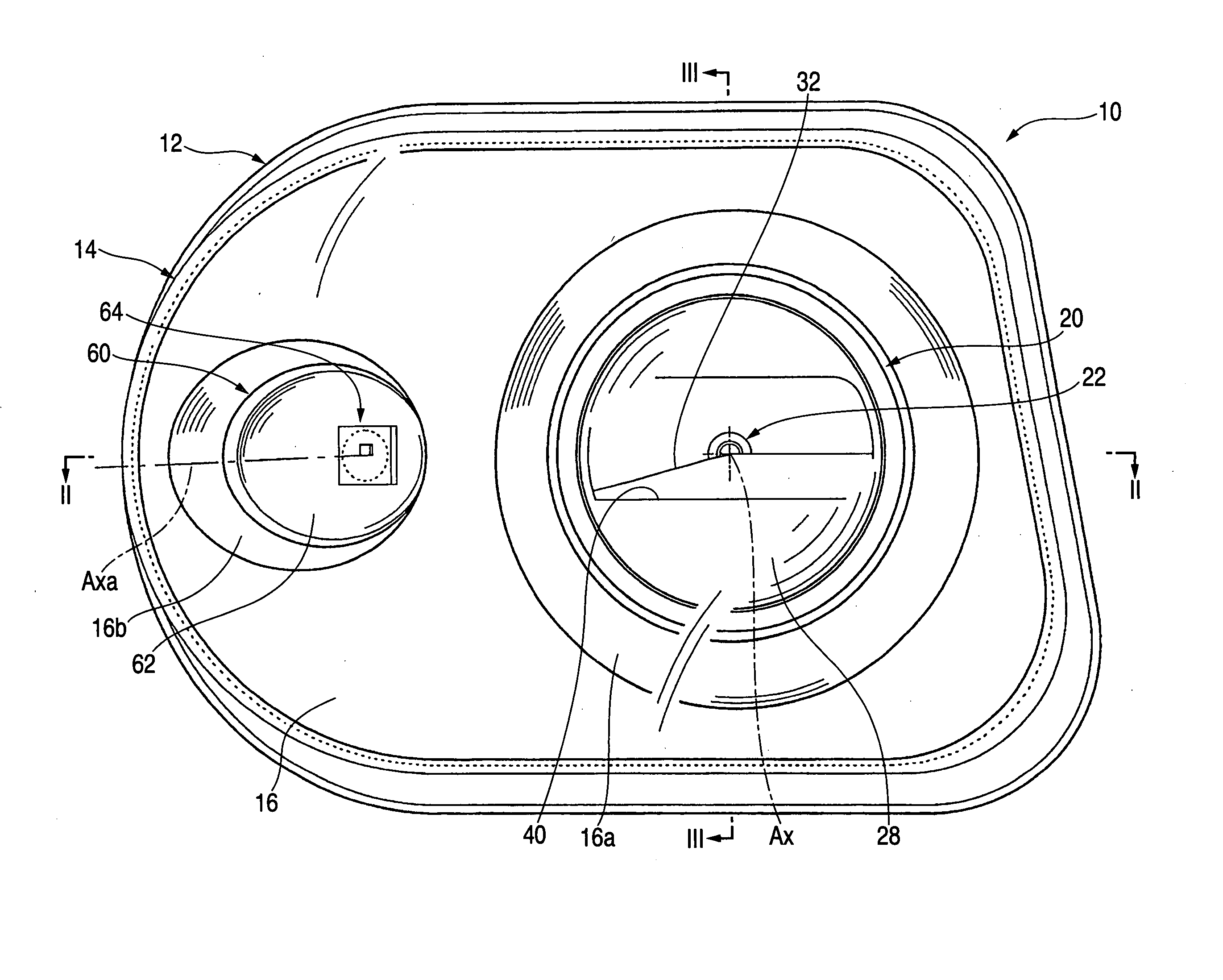
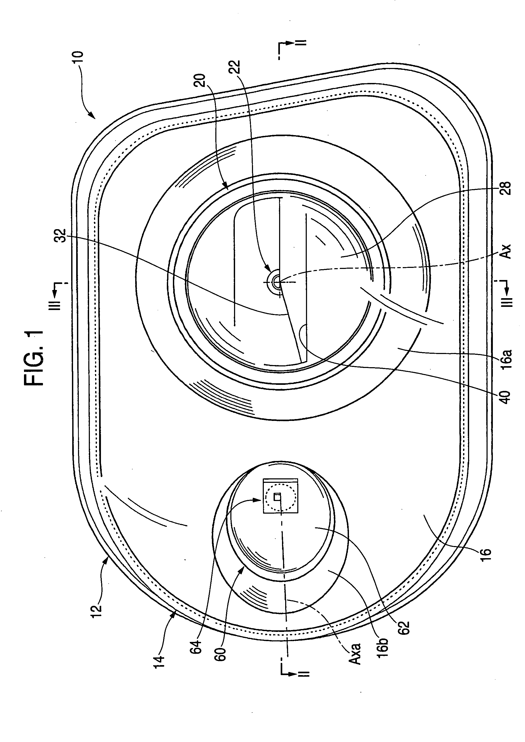
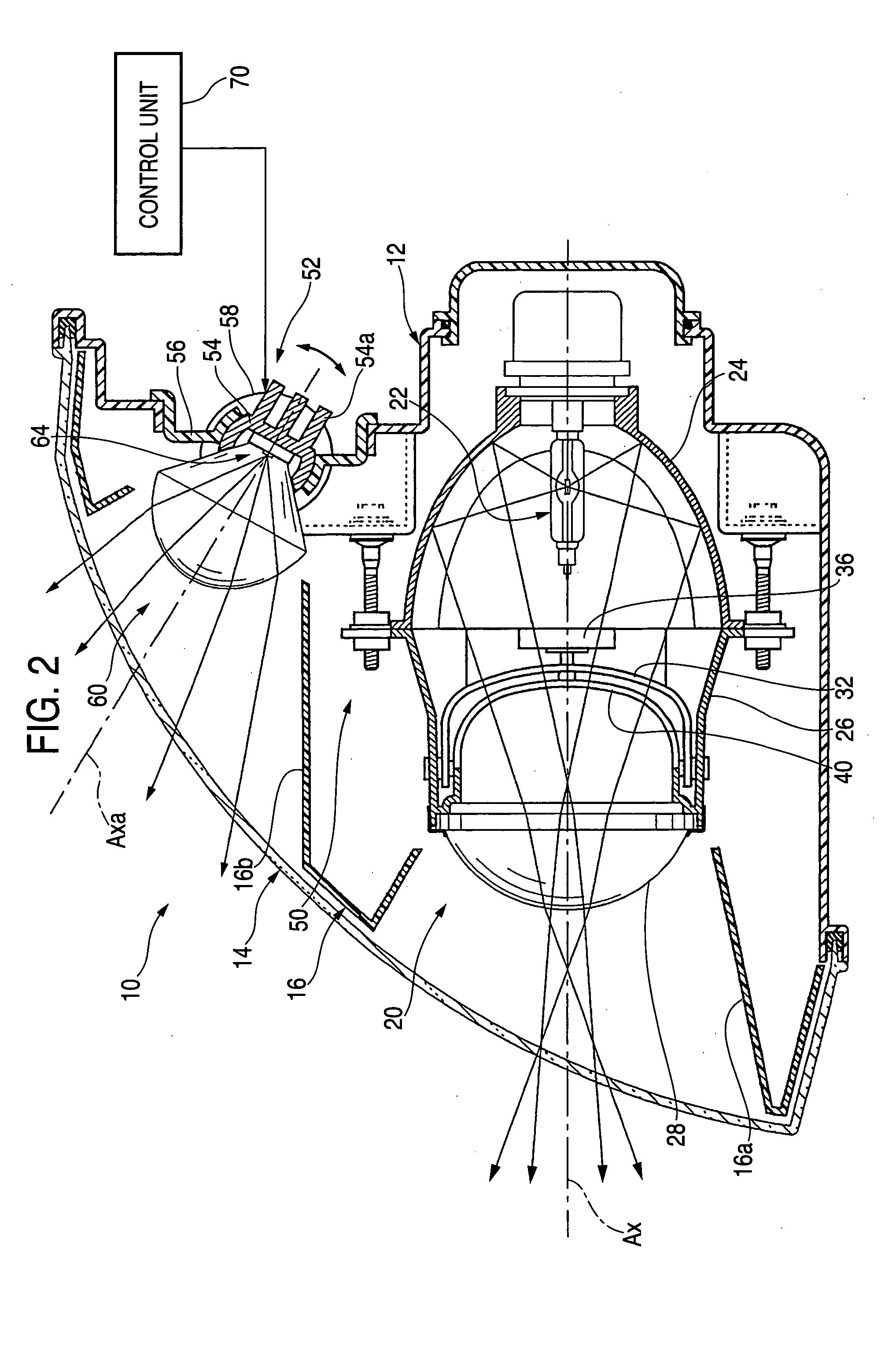
[0045]FIG. 1 is a front view showing a vehicular headlamp according to an embodiment of the invention, and FIGS. 2 and 3 are a sectional view taken along a line II-II of FIG. 1 and a sectional view taken along a line III-III thereof, respectively.

[0046] A vehicular headlamp 10 according to the exemplary, non-limiting embodiment of the present invention is a lamp piece arranged on the right side of a front end portion of a vehicle and constructed by a constitution in which a basic lamp piece unit 20 (e.g., first lamp piece unit) and an additional lamp piece unit 60 (e.g., second lamp piece unit) are inside a lamp chamber formed by a lamp body 12 and a transparent light transmitting cover 14 in a state of being arranged contiguously to the left and right.

[0047] Further, inside the lamp chamber is an inner panel 16 along the light transmitting cover 14. Cylindrical opening portions 16a, 16...


PUM


Abstract

Whereas a light source bulb is used as a light source of a basic lamp piece unit which needs a large amount of irradiating light, with regard to an additional lamp piece unit lighted on and off repeatedly in accordance with a situation of running a vehicle, a semiconductor light emitting element having a fast response speed in being lighted on and off and excellent in durability against repeatedly lighting on and off the semiconductor light emitting element 64 as a light source thereof. Thereby, light can be irradiated in correspondence with the situation of running the vehicle and life of the light source can sufficiently been ensured. Further, the additional lamp piece unit is made to be able to be compactly constituted to promote a degree of freedom of arranging the additional lamp piece unit.

Description

[0001] This application claims foreign priority based on Japanese Patent Application no. JP2003-374060, filed on Nov. 4, 2003, the contents of which is incorporated by reference. BACKGROUND OF THE INVENTION [0002] 1. Technical Field [0003] The present invention relates to a vehicular headlamp including a basic lamp piece unit capable of forming a light intensity distribution pattern for a low beam and an additional lamp piece unit capable of being lighted temporarily when lighting the basic lamp piece unit. [0004] 2. Background of the Related Art [0005] Generally, a vehicular headlamp forms a light intensity distribution pattern for a low beam having a cutoff line at an upper end edge thereof and is constituted to ensure front optical recognizability of a driver of one's own vehicle, such that glare is not cast to a driver of a vehicle running on an opposite lane or the like. [0006] In this case, as described in, for example, JP-A-2000-238576 or JP-A-2001-213227, a related art vehic...

Claims


Application Information

Patent Timeline
Patent Type & Authority Applications(United States)
IPC IPC(8): B60Q1/12B60Q1/18F21S8/10F21V14/00B60Q1/08F21V14/02F21V14/08F21W101/10F21Y101/02
CPCB60Q1/0041B60Q1/12B60Q1/18B60Q2300/054B60Q2300/122F21Y2101/02B60Q2300/322F21S48/115F21S48/1186F21S48/1768F21S48/25B60Q2300/312F21Y2115/10F21S41/141F21S41/143F21S41/17F21S41/683F21S43/50
Inventor ISHIDA, HIROYUKITATSUKAWA, MASASHISAZUKA, KIYOSHI
Owner KOITO MFG CO LTD
Why Eureka
Try Eureka