Antenna device

Inactive Publication Date: 2005-05-05
NEC CORP
View PDF7 Cites 45 Cited by
  • Summary
  • Abstract
  • Description
  • Claims
  • Application Information

AI Technical Summary

Benefits of technology

[0011] It is an object of the present invention to provide an antenna device which is capable of exhibiting satisfac

Problems solved by technology

However, the conventional art techniques described above cause the following problems.
Such a use would result in variations in im

Method used


Image

  • Antenna device
  • Antenna device
  • Antenna device

Examples


first embodiment

[0022] the present invention will be described in detail with reference to the accompanying drawings.

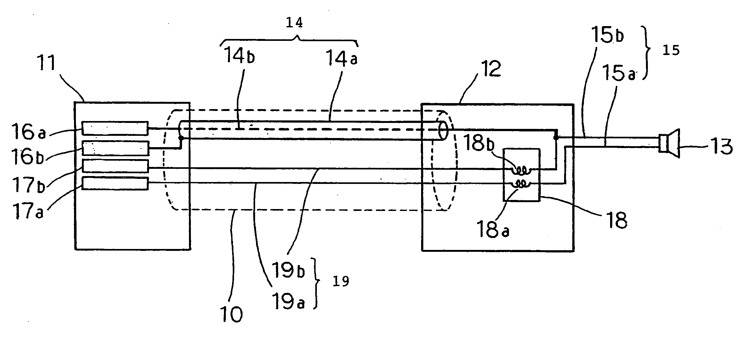
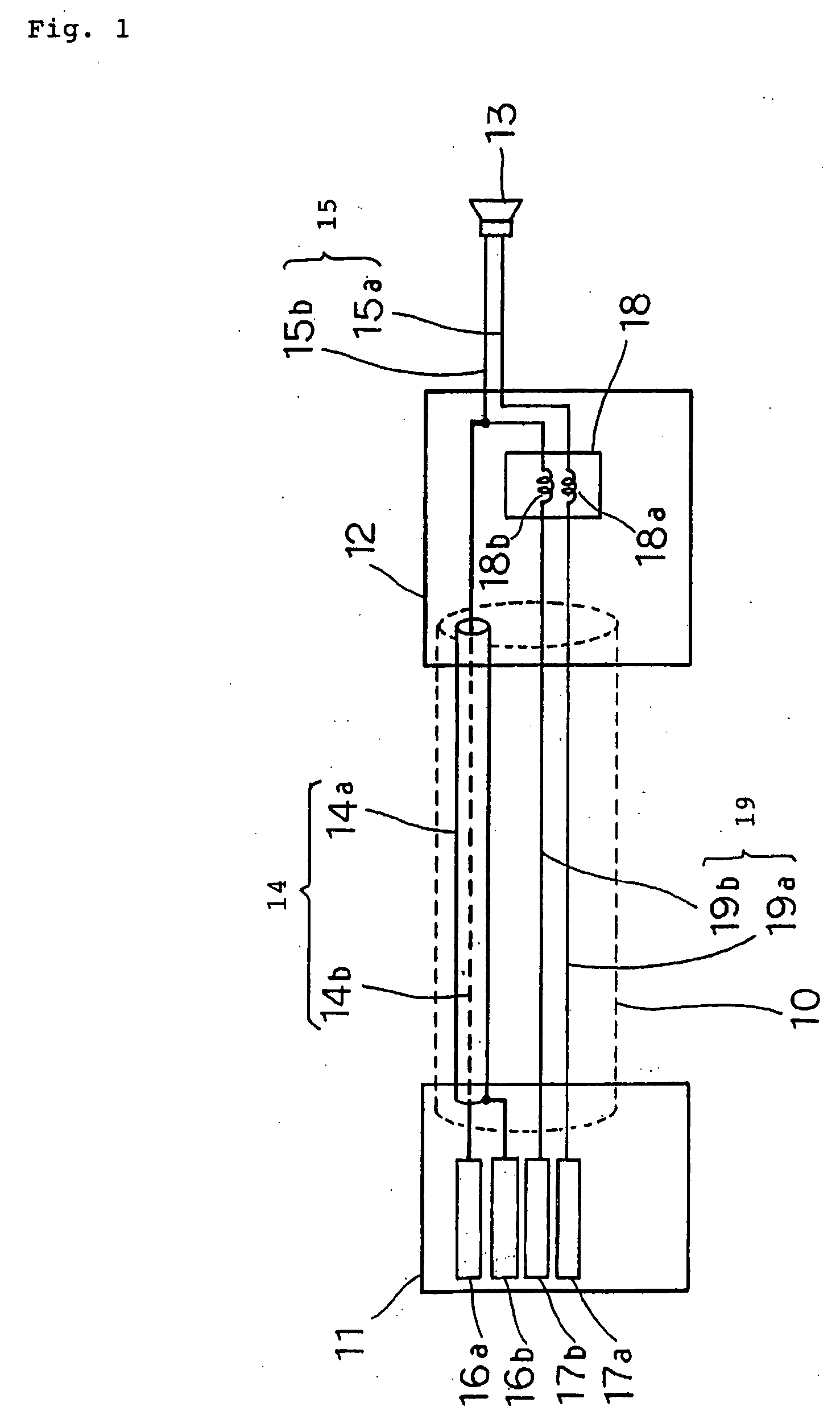
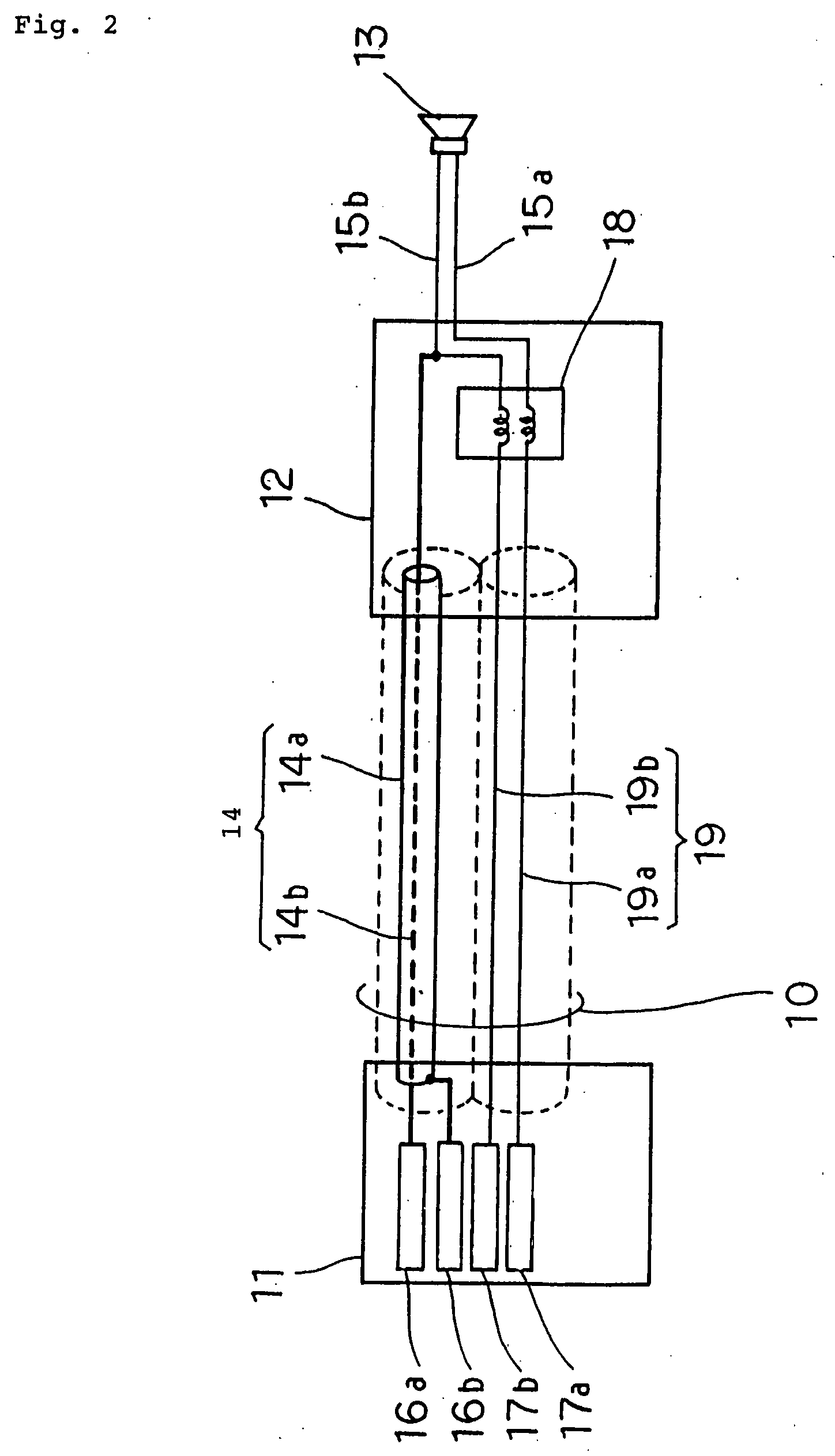
[0023]FIG. 1 is a diagram illustrating an antenna device according to the first embodiment. The antenna device of this embodiment is integrated with an earphone which is connected to a compact wireless equipment.

[0024] Referring to FIG. 1, the antenna device comprises earphone cable 10, connector 11, branch 12, earphone signal line pair 15, and ear receiver 13. Connector 11 is connected to branch 12 through earphone cable 10. Branch 12 is connected to ear receiver 13 through earphone signal line pair 15.

[0025] Earphone cable 10 comprises coaxial line 14 composed of shield line 14a and core line 14b; earphone signal line pair 19 composed of earphone audio line 19b and earphone GND line 19a; and a single sheath which covers both coaxial line 14 and earphone signal line pair 19. Connector 11 comprises antenna terminal 16a, antenna GND terminal 16b, earphone terminal 17a, and earphone ...

second embodiment

[0035] Description will be next made of the present invention.

[0036]FIG. 3 is a diagram illustrating an antenna device according to the second embodiment. The antenna device of this embodiment differs from the first embodiment in that the antenna device is integrated with a stereo-type earphone.

[0037] Referring to FIG. 3, the antenna device comprises earphone cable 20, connector 21, branch 22, earphone signal line pairs 25A, 25B, and ear receivers 23A, 23B. Connector 21 is connected to branch 22 through earphone cable 20. Branch 22 is connected to ear receiver 23A through earphone signal line pair 25A, while branch 22 is connected to ear receiver 23B through earphone signal line pair 25B.

[0038] Earphone cable 20 comprises coaxial line 24 composed of shield line 24a and core line 24b; earphone signal lines 29 composed of earphone L-ch audio line 29a, earphone R-ch audio line 29b, and earphone GND line 29c; and a single sheath which covers both coaxial line 24 and earphone signal li...

third embodiment

[0047] Description will next be made of the present invention.

[0048] An antenna device of the third embodiment is similar to the second embodiment in that the antenna device is integrated with a stereo-type earphone. The third embodiment, however, differs from the second embodiment in that coaxial lines are used between branch 22 and ear receivers 23A, 23B, and shield lines of the coaxial lines function as antenna elements. In this way, L-ch and R-ch audio signals and signals received by the antenna elements can be separated between branch 22 and ear receivers 23A, 23B.

[0049]FIG. 4 is a diagram illustrating the antenna device according to the third embodiment. In the antenna device of the third embodiment illustrated in FIG. 4, the following description will focus on the differences from the antenna device of the second embodiment. Branch 22 is connected to ear receiver 23A through a coaxial line which has earphone L-ch audio line 25a and earphone L-ch GND line 25b passing through ...


PUM


Abstract

An antenna device disclosed herein is integrated with an earphone for generating sound from an ear receiver, and connected to a wireless equipment through a connector to transmit an audio signal applied from the wireless equipment to the connector through a plurality of earphone signal lines. An antenna element lies between the ear receiver and an intermediate position of an earphone signal line for transmitting the audio signal from the connector to the ear receiver. A branch is disposed at the intermediate position for preventing a high frequency signal on each of the plurality of earphone signal lines from passing therethrough, and for passing the audio signal therethrough to extract a signal received by the antenna element. A coaxial line transmits the signal received by the antenna element and extracted by the branch to the connector through a core line possessed thereby.

Description

BACKGROUND OF THE INVENTION [0001] 1. Field of the Invention [0002] The present invention relates to an antenna device for a compact wireless equipment, and more particularly, to an antenna device which is incorporated in an earphone connected to a compact wireless equipment. [0003] 2. Description of the Related Art [0004] In the field of compact wireless equipments, importance is placed on improvements on portability which can be accomplished by reducing the size and weight of the equipment. [0005] A portable FM radio may be used with an earphone which incorporates an antenna. The use of an earphone with a built-in antenna contributes to improved portability of FM radio because an antenna need not be additionally provided. [0006] In an antenna built-in earphone for use with a portable FM radio, a cable of the entire earphone from an earphone jack is utilized as an antenna. The earphone for use with a compact wireless equipment such as a portable FM radio typically has a cable of on...

Claims


Application Information

Patent Timeline
IPC IPC(8): H01Q1/46G02C1/00H01Q1/27H01Q1/44H01Q1/52H01Q9/30H04B1/18H04R25/00
CPCH01Q1/44H01Q1/273
Inventor HARANO, NOBUYA
Owner NEC CORP
Why Eureka
Try Eureka