Eye bolt

Inactive Publication Date: 2005-05-05
BECKERS LUDWIG
View PDF8 Cites 10 Cited by
  • Summary
  • Abstract
  • Description
  • Claims
  • Application Information

AI Technical Summary

Benefits of technology

[0008] The invention is therefore based on the problem of creating a solution which improves t

Problems solved by technology

But this also means that larger carabiners can be used which otherwise could not be, due to a bu

Method used


Image

  • Eye bolt
  • Eye bolt

Examples


Example

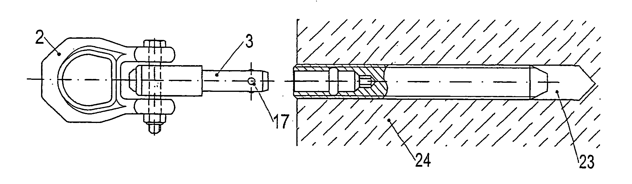
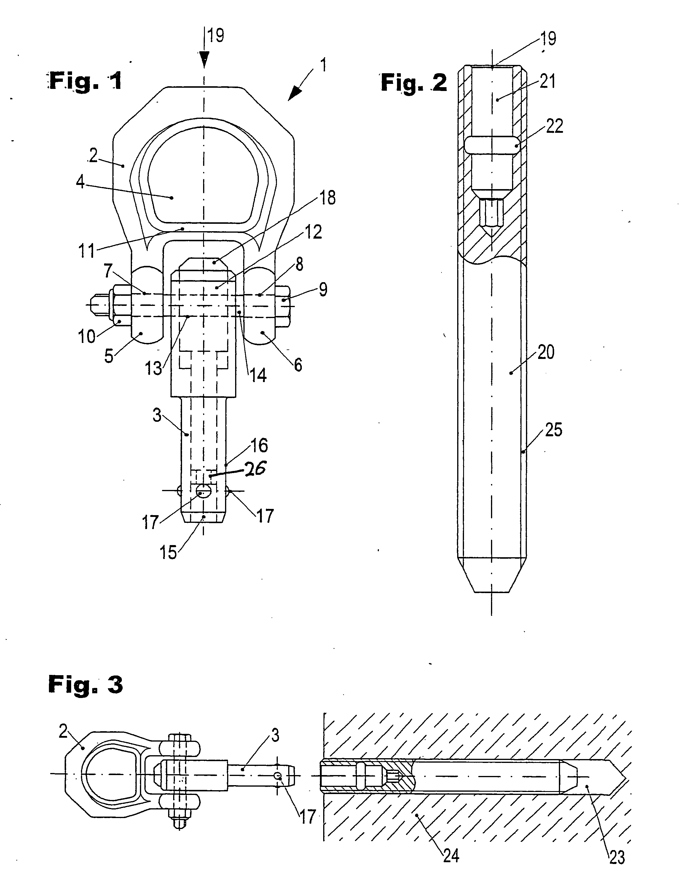
[0020] The fastening element referred to as a whole in FIG. 1 as 1, in the form of an eye bolt, comprises a ring body 2 and a hollow fastening bolt 3. Ring body 2 encompasses or encircles a ring opening 4 and is extended in the manner of a shackle externally on one side outside the ring opening 4 by shackle ends 5, 6. In shackle ends 5, 6, bores 7, 8 are formed through which a cap screw 9 is passed and is screwed tight at the end opposite the screw head with a self-locking nut 10. An end area 12 of fastening bolt 3 is disposed in the space framed by shackle ends 5, 6 and a cross-strut 11 of ring body 2. This end area 12 has a cross hole 13, through which cap screw 9 with its rod-shaped or pin-shaped fastening element part 14 punches. In its end area 15 located opposite end area 12, fastening bolt 3 has symmetrically-disposed openings on one perimeter area of its surface shell 16, through which balls 17 protrude with a part of their surface from the surface shell 16 of the fastening ...


PUM


Abstract

A fastening element in the form of an eye bolt, which has a ring body encompassing a ring opening. The ring body is connected with an end area of a fastening bolt, which has, at a distance from said end area, in its fastening position, balls with a part of their surface protruding from the surface shell of the fastening bolt. The balls are held in their fastening position by a bolt element guided within the fastening bolt. The bolt element is axially longitudinally moveable against the force of a spring and is intended to provide a solution which improves the characteristics of use and handling of such an actuation element. This is achieved by the fact that the ring body is extended in the manner of a shackle beyond its ring opening and the end area of the fastening bolt is fixed so as to pivot between the shackle ends.

Description

BACKGROUND OF THE INVENTION [0001] 1. Field of the Invention [0002] The invention relates to a fastener in the form of an eye bolt, which has a ring body encompassing a ring opening, said ring body being connected with an end area of a fastening bolt. The fastening bolt has balls with a part of their surface protruding from the surface shell of the fastening bolt, the balls being held in their fastening position by means of a bolt element guided within the fastening bolt. The bolt element is axially longitudinally moveable against the force of a spring. The invention also relates to a fastening system consisting of the fastening element and an engaging and disengaging sleeve receiving the fastening bolt with an inner groove adapted to the dimension of the spherical areas protruding from the surface shell of the fastening bolt. [0003] 2. The Prior Art [0004] Such fastening elements and fastening systems are known as “removable anchorage points”. The sleeve usually has an external thr...

Claims


Application Information

Patent Timeline
IPC IPC(8): F16B13/00F16B19/10F16B21/16F16B25/00F16B35/06F16B45/00
CPCF16B13/00F16B19/109F16B45/00F16B25/00F16B35/06F16B21/165F16B45/002
Inventor BECKERS, LUDWIG
Owner BECKERS LUDWIG
Why Eureka
Try Eureka