Method and system for installation and control of a utility device

a technology for installing and controlling utility devices, applied in the direction of process and machine control, cleaning equipment, instruments, etc., can solve the problems of human error affecting the reliability, affecting the quality of the wash process performed by the resident warewashing machine, and limited current approach

Active Publication Date: 2005-05-05
ECOLAB USA INC
View PDF63 Cites 24 Cited by
  • Summary
  • Abstract
  • Description
  • Claims
  • Application Information

AI Technical Summary

Benefits of technology

[0008] In accordance with the present invention, the above and other problems are solved by a computer-implemented method for configuring a utility device in a service environment where the utility device is intended to operate to perform at least one service. The method provides a graphical user interface through which a field service person inputs one or more parameters associated with the service environment. The method then analyzes these “environmental” parameters to determine operational settings for use by the utility device in performing the service. After the operational settings have been determined, the utility device is deployed for operation in the service environment based on these operational settings.

Problems solved by technology

This current approach is limited in that these operational settings are defined based on manual approximations by the field service persons taking into account the various types of environmental information.
As with any manual approximation, the chance of human error affects the reliability that wash processes by the machine will satisfy a desired, or sometimes regulated, quality.
Further, if any of this environmental information were to change without the appropriate operational settings also being modified accordingly, the quality of the wash processes performed by the resident warewash machine is consequently affected.
Unfortunately, thus, it may be days, if not weeks, until a warewash machine associated with such an environmental change is serviced.

Method used


Image

  • Method and system for installation and control of a utility device
  • Method and system for installation and control of a utility device
  • Method and system for installation and control of a utility device

Examples


Embodiment Construction

[0024] The present invention and its various embodiments are described in detail below with reference to the figures. When referring to the figures, like structures and elements shown throughout are indicated with like reference numerals. Objects depicted in the figures that are covered by another object, as well as the reference annotations thereto, are shown using dashed lines.

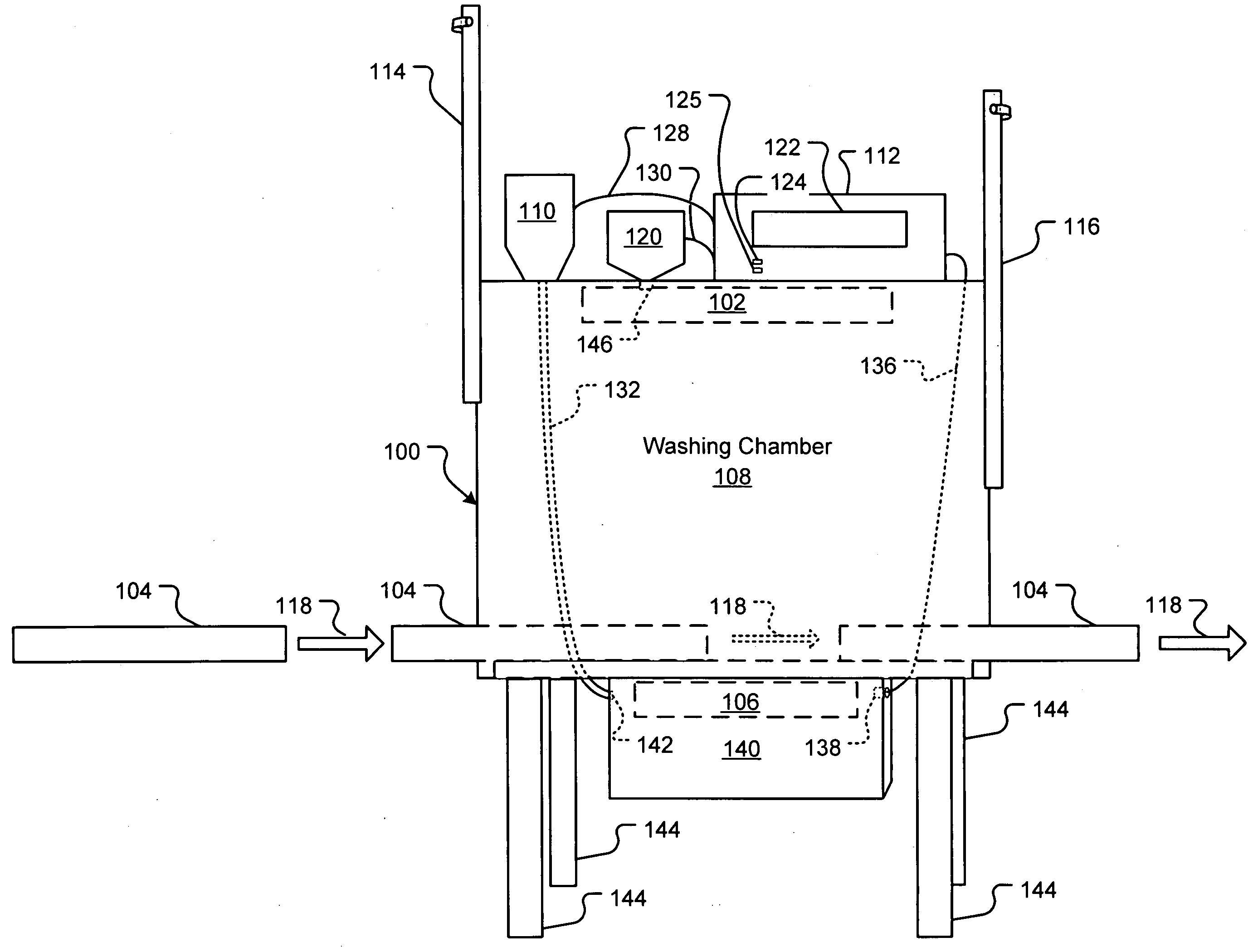
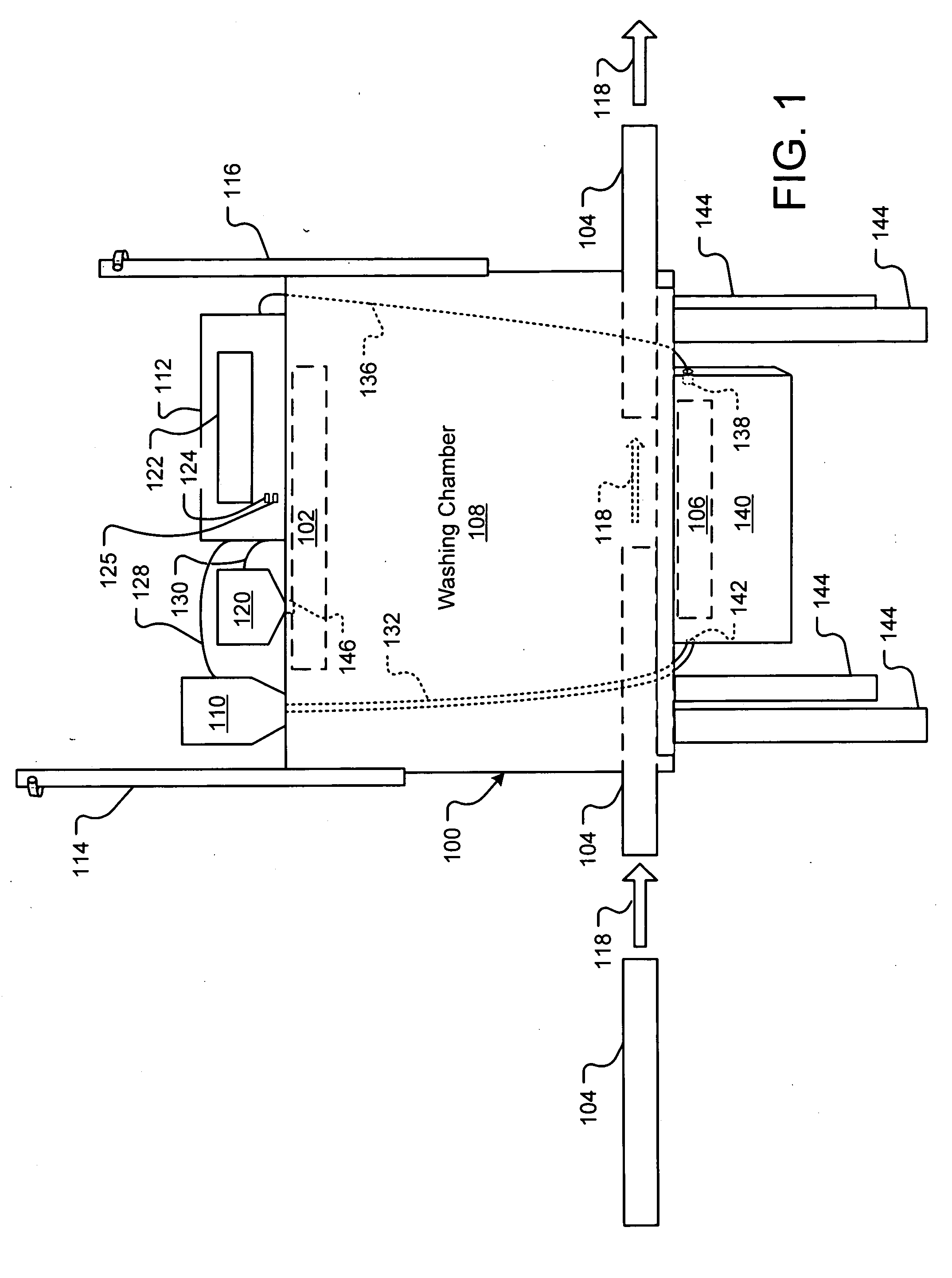
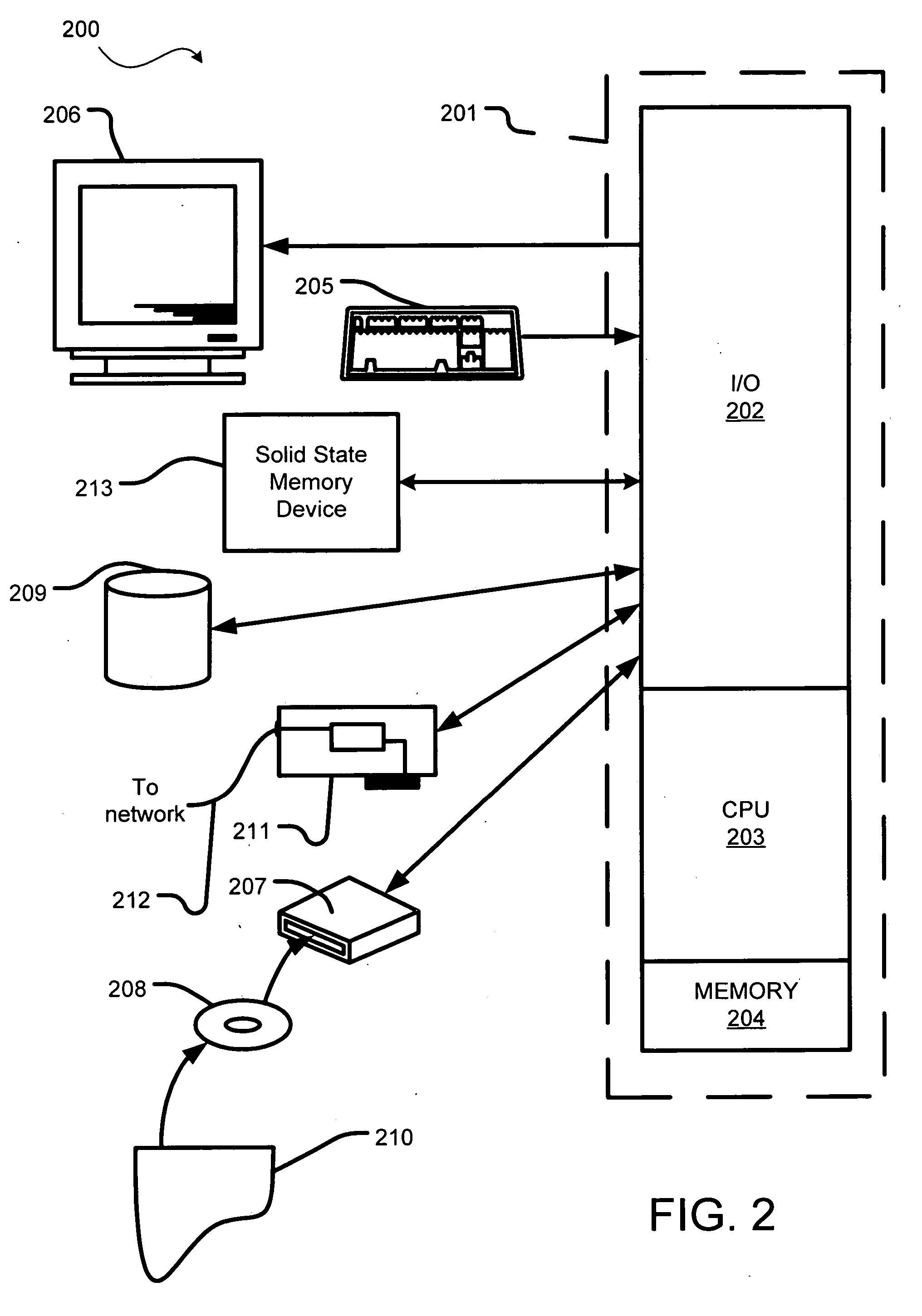
[0025] In an embodiment, the present invention relates to a computer-implemented process for configuring and administering control over operations of a utility device. For illustration only, and not by means of limitation, the utility device is described herein as being a cleaning apparatus, and more particularly a commercial dishwasher, which is also referred to as a “warewash machine.” In this embodiment, logical operations of the present invention are performed by a warewash controller communicatively coupled to a product dispenser processor and / or a rinse module, wash module and / or various other process...


PUM


Abstract

A system and method is disclosed for configuring and administering control over operations of a utility device. The utility device is described herein as being a warewash machine, but other utility devices are contemplated. A warewash controller administers control over operations of the warewash machine based on operational settings defined by the process disclosed herein. The operational settings are derived based on environmental parameters (e.g., water type, soil level, selected chemical product, etc.) specified by a field service person through a graphical user interface. If an environmental parameter is changed during the operational life cycle of the warewash machine, the operational settings are modified to accommodate for such a change. Thus, the service performed by the warewash machine is maintained at a consistent quality regardless of changes in the environment. A method for selecting the specific chemical product that will be input as an environmental parameter is also disclosed.

Description

TECHNICAL FIELD [0001] The invention relates generally to a utility device, and more particularly to installation of the utility device within an operational environment. BACKGROUND [0002] A warewash machine is a utility dishwasher used in many restaurants, healthcare facilities and other locations to efficiently clean and sanitize cooking and eating articles, such as, dishes, pots, pans, utensils and other cooking equipment. Articles are placed on a rack and provided to a washing chamber of the warewash machine. In the chamber, rinse agents and cleaning products are applied to the articles over a predefined period of time referred to as a “wash cycle.” A wash cycle includes a cleaning cycle and a rinsing cycle. At least one cleaning product is applied to the articles during the cleaning cycle. The cleaning product is typically a chemical solution formed by dissolving one or more chemical products in water. The term chemical product is used broadly to encompass, without limitation, ...

Claims


Application Information

Patent Timeline
Patent Type & Authority Applications(United States)
IPC IPC(8): D06F33/37D06F34/28G06F17/00
CPCA47L15/0021D06F2210/00A47L15/0063A47L15/241A47L15/4293A47L2301/026A47L2401/04A47L2401/11A47L2401/12A47L2401/30A47L2501/07A47L2501/30D06F33/02D06F2202/02D06F2204/02A47L15/0055D06F34/28D06F33/37D06F2103/20D06F2105/42
Inventor PETERSON, JEFF WILLIAMMAY, ROBERTFLESHER, DANROLANDO, JOHNSOWLE, EDLENTSCH, STEVENHOWES, RONALD JR.
Owner ECOLAB USA INC
Why Eureka
Try Eureka