
Humane tubular trap, remote trap monitoring system and method and programs for monitoring multiple traps

a trap and remote monitoring technology, applied in the field of trap monitoring systems for humane tubular traps, can solve the problems of affecting the service life of the trap, the inner wall of the trap does not provide any purchase for the animal, and the double wall construction is extremely rugged, so as to prevent heat prostration and thermal distress, attract and calm the animals, and prolong the service life

Inactive Publication Date: 2005-05-12
VORHIES JAMES FREDERICK +2
View PDF21 Cites 132 Cited by
  • Summary
  • Abstract
  • Description
  • Claims
  • Application Information

AI Technical Summary

Benefits of technology

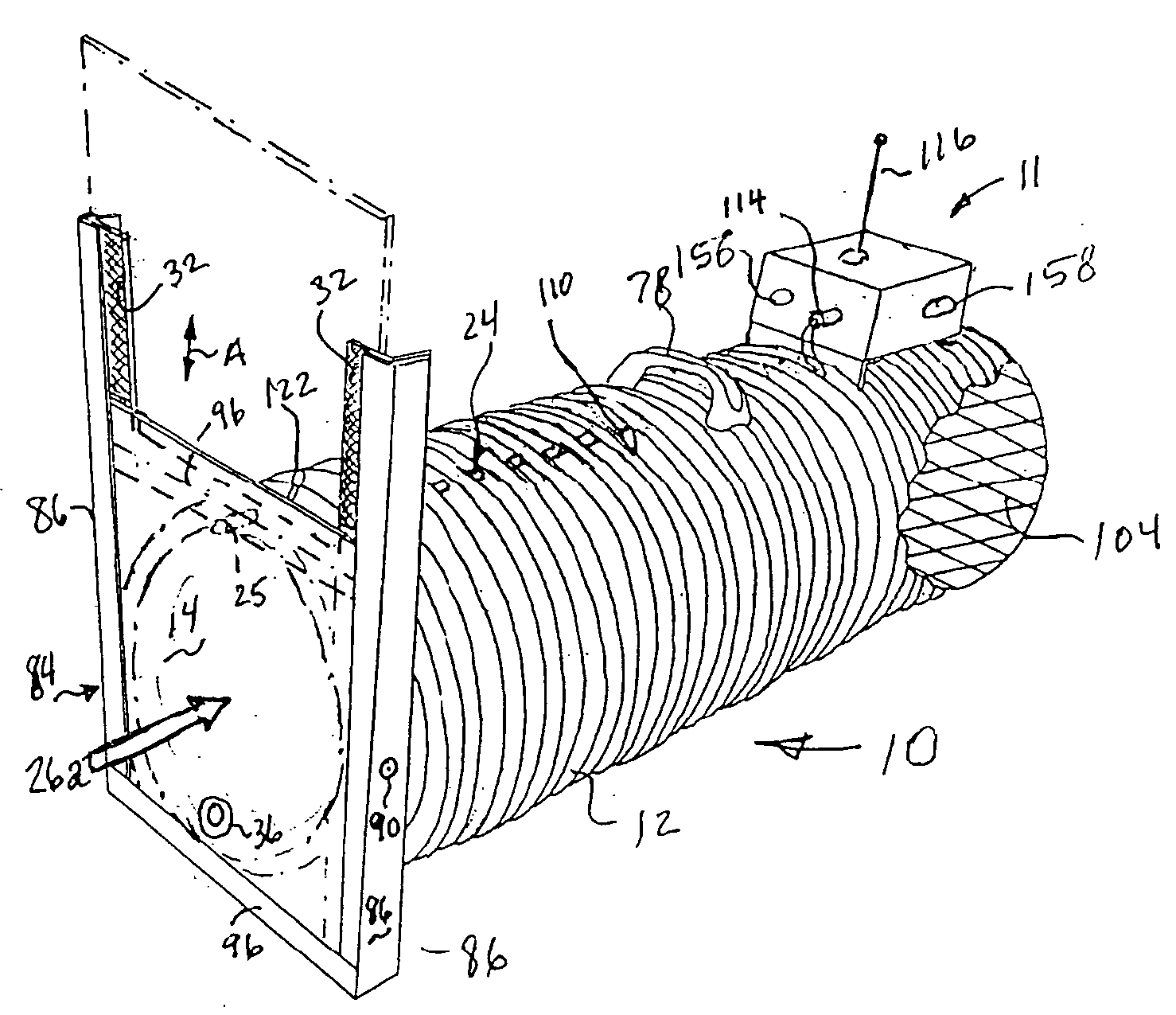
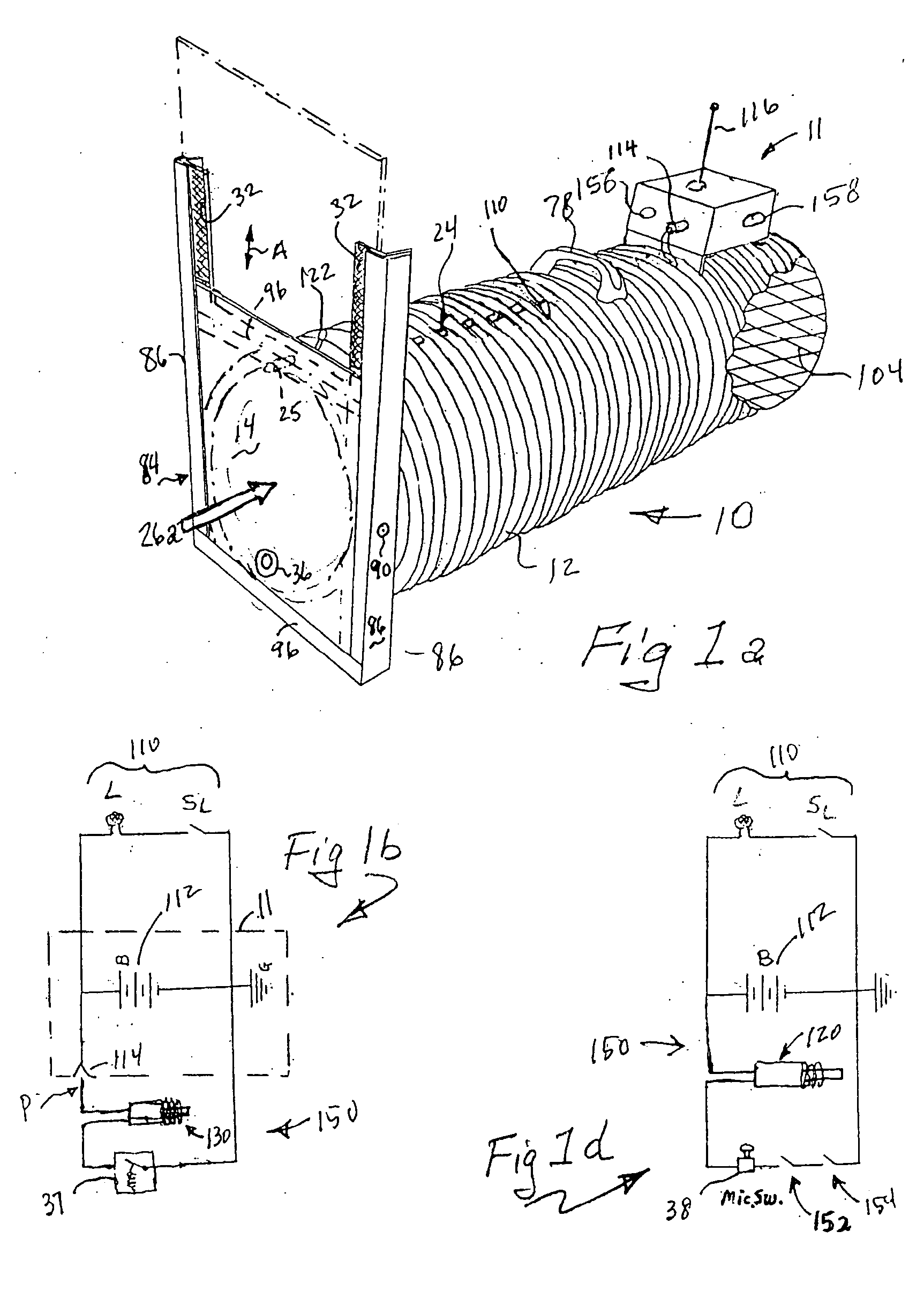
[0017] The opaque, double walls and tubular configuration of the trap both attracts and calms the animals. The double walls provide insulation, preventing heat prostration and thermal distress to the animal. In many States, it is illegal to use meat for bait that is visible to birds of prey. Thus, the opaque tube prevents the bait from being visible, and protects the bait from weather.
[0019] Thus, the inventive trap provides a mode of trapping that is very humane, in that it is not a leg or body grip type trap, does not permit the animal injury-promoting escape options, shelters the animal from the elements and heat, visually shelters the bait, visually shelters the trapped animal from predators, and through its communications module, permits prompt retrieval of an un-injured animal.
[0023] The remote monitoring aspects of the invention provides a method for trappers to monitor from a single “home” base, many traps simultaneously, the number ranging easily in the hundreds, depending on the geographic extent of the area of trapping. Unlike fishing with a line, a trap placed in a field has no “line” back to the trapper. However, under the inventive system, the trapper can visually and / or audially check when individually located traps are tripped. Thus, the need for checking each trap each morning is not required; each trap is serviced when tripped based on the status alert radioed to home base from each trap when that event occurs.
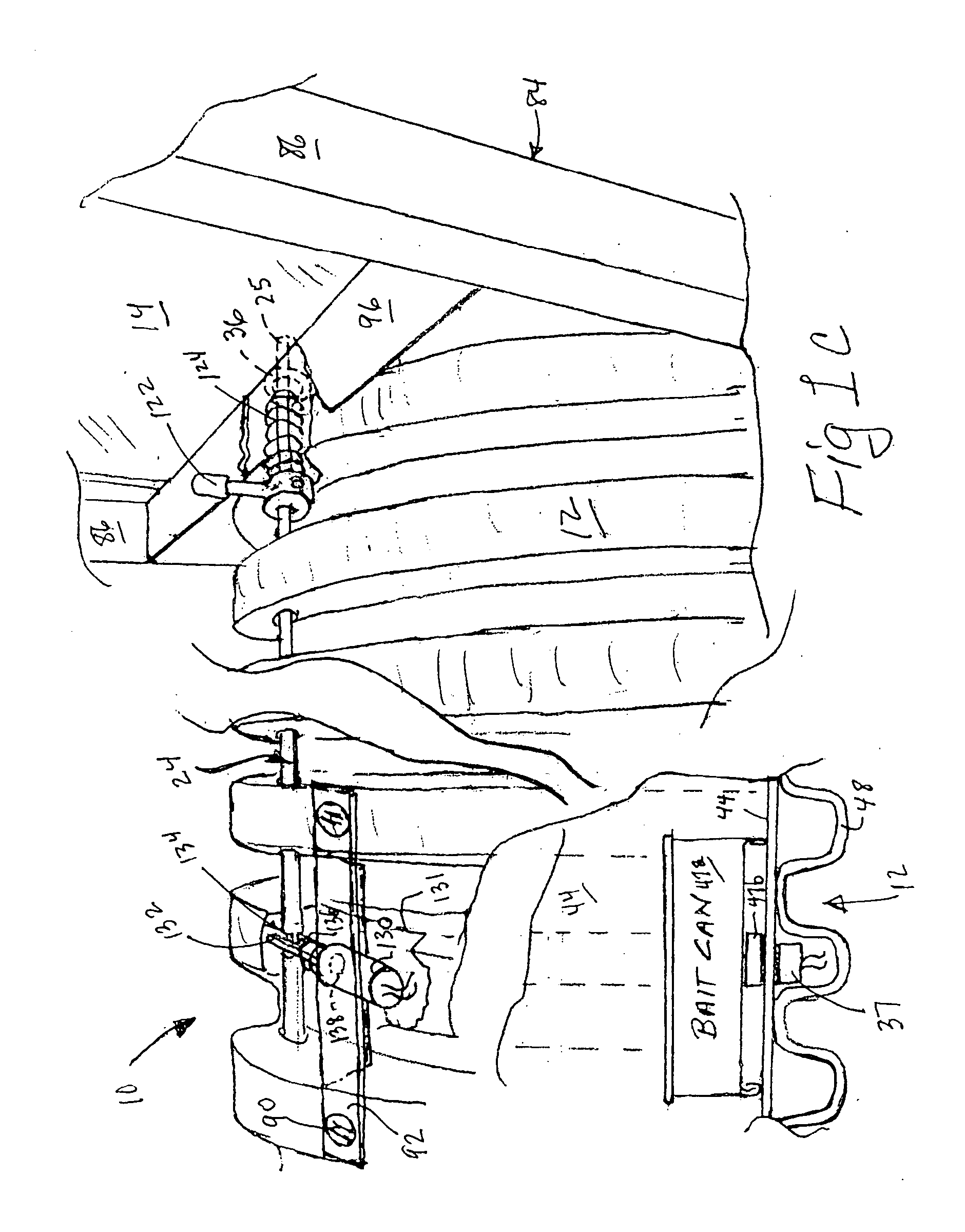
[0027] In one important alternative embodiment, the door is held in its “ready”, un-triggered, raised position by a solenoid pin, or a spring-biased rod having a solenoid catch, that extends through a hole in the door adjacent the bottom of the door. When the trap is tripped, the solenoid pin or rod retracts, the door descends and it engages a switch that opens the circuit, killing power to the solenoid door release latch pin or the rod catch solenoid. The spring biases the solenoid pin or the rod to the extended position, positively latching the door in the closed position through a hole adjacent the top of the door (the “trap sprung” hole). However, there is enough play in the trap sprung hole that a slight lift of the door releases the switch, energizes the solenoid and retracts the pin from the sprung position hole. This permits the door to be raised fully. This function is a safety system in the event a child crawls into the trap. Although an animal cannot raise the closed / lowered “sprung” position door, a human can by engaging a finger in the lower “set” position hole and sliding the door upward. The slight oversize of the “sprung” position hole permits the door to move upward just enough to open the door switch, killing power to the solenoid and releasing the pin. The door can thus be raised easily to permit egress of the child. In addition, the door can be maintained in the lowered, sprung position by actuating an ON-OFF switch provided in the circuit.

Problems solved by technology

In addition, the smooth, almost slippery, plastic inner wall of the traps does not provide any purchase for the animal to attempt escape.
The double wall construction is extremely rugged, lending itself well to remote field use with long service life.

Method used


Image

  • Humane tubular trap, remote trap monitoring system and method and programs for monitoring multiple traps
  • Humane tubular trap, remote trap monitoring system and method and programs for monitoring multiple traps
  • Humane tubular trap, remote trap monitoring system and method and programs for monitoring multiple traps

Examples


Embodiment Construction

[0053] The following detailed description illustrates the invention by way of example, not by way of limitation of the scope, equivalents or principles of the invention. This description will clearly enable one skilled in the art to make and use the invention, and describes several embodiments, adaptations, variations, alternatives and uses of the invention, including what is presently believed to be the best modes of carrying out the invention.

[0054] In this regard, the invention is illustrated in the several figures, and is of sufficient complexity that the many parts, interrelationships, and sub-combinations thereof simply cannot be fully illustrated in a single patent-type drawing. For clarity and conciseness, several of the drawings show in schematic, or omit parts that are not essential in that drawing to a description of a particular feature, aspect or principle of the invention being disclosed. Thus, the best mode embodiment of one feature may be shown in one drawing, and t...


PUM


Abstract

Tube-type animal trap systems for the humane non-injurious, non-invasive trapping of animals, and to methods and systems for electronic remote trap monitoring and management. The invention includes mechanical and electric / electronic, tube-type traps, and to electronic data communications systems that enable remote monitoring of the status of any type of trap (e.g., is the trap tripped or not). Computer systems at a remote home base permit simultaneous management of multiple traps in the field, including enabling management via the Internet.

Description

CROSS REFERENCE TO RELATED APPLICATIONS [0001] This application is the Regular U.S. Application related to and based on Provisional Application Ser. No. 60 / 502,430 filed Sept. 12, 2003 under the title Tubular Trap, and on Provisional Application Ser. No. 60 / 509,881 filed Oct. 8, 2003, entitled Tubular Trap II, both filed by two of the same inventors (the Vorhies), the priorities of which applications are claimed under 35 US Code §§ 119 and 120, the entire subject matter of which applications are hereby incorporated by reference.FIELD [0002] The invention pertains to the trapping industry, and more particularly to humane animal tube-type or tunnel-type trap systems for the non-injurious, non-invasive trapping of animals, and to methods and systems for electronic remote trap monitoring and management. The invention includes mechanical and electric / electronic, humane, tube-type traps, and to electronic data communications systems that enable remote monitoring of the status of any type ...

Claims


Application Information

Patent Timeline
IPC IPC(8): A01M23/02A01M23/18A01M23/20A01M31/00G06F19/00G08C17/02H04L12/70
CPCA01M23/18A01M31/002A01M23/20
Inventor VORHIES, JAMES FREDERICKVORHIES, JAMES FRANCISCARTER, WILLIAM E. JR.
Owner VORHIES JAMES FREDERICK
Learn More