Key structure of computer keyboard

a computer keyboard and key structure technology, applied in the field of key structure, can solve the problem of high cost of manufacturing integrally formed elastic assemblies, and achieve the effect of strengthening bonding

Inactive Publication Date: 2005-05-12
CHICONY ELECTRONICS
View PDF8 Cites 10 Cited by
  • Summary
  • Abstract
  • Description
  • Claims
  • Application Information

AI Technical Summary

Benefits of technology

[0006] An object of the present invention is to provide a key structure with an elastic contact body having the bottom surface formed as an embossed surface provided with a cross-striped structure. The bonding area of the bottom surface of the elastic ...

Problems solved by technology

However, the manufacture of the integr...

Method used


Image

  • Key structure of computer keyboard
  • Key structure of computer keyboard
  • Key structure of computer keyboard

Examples


first embodiment

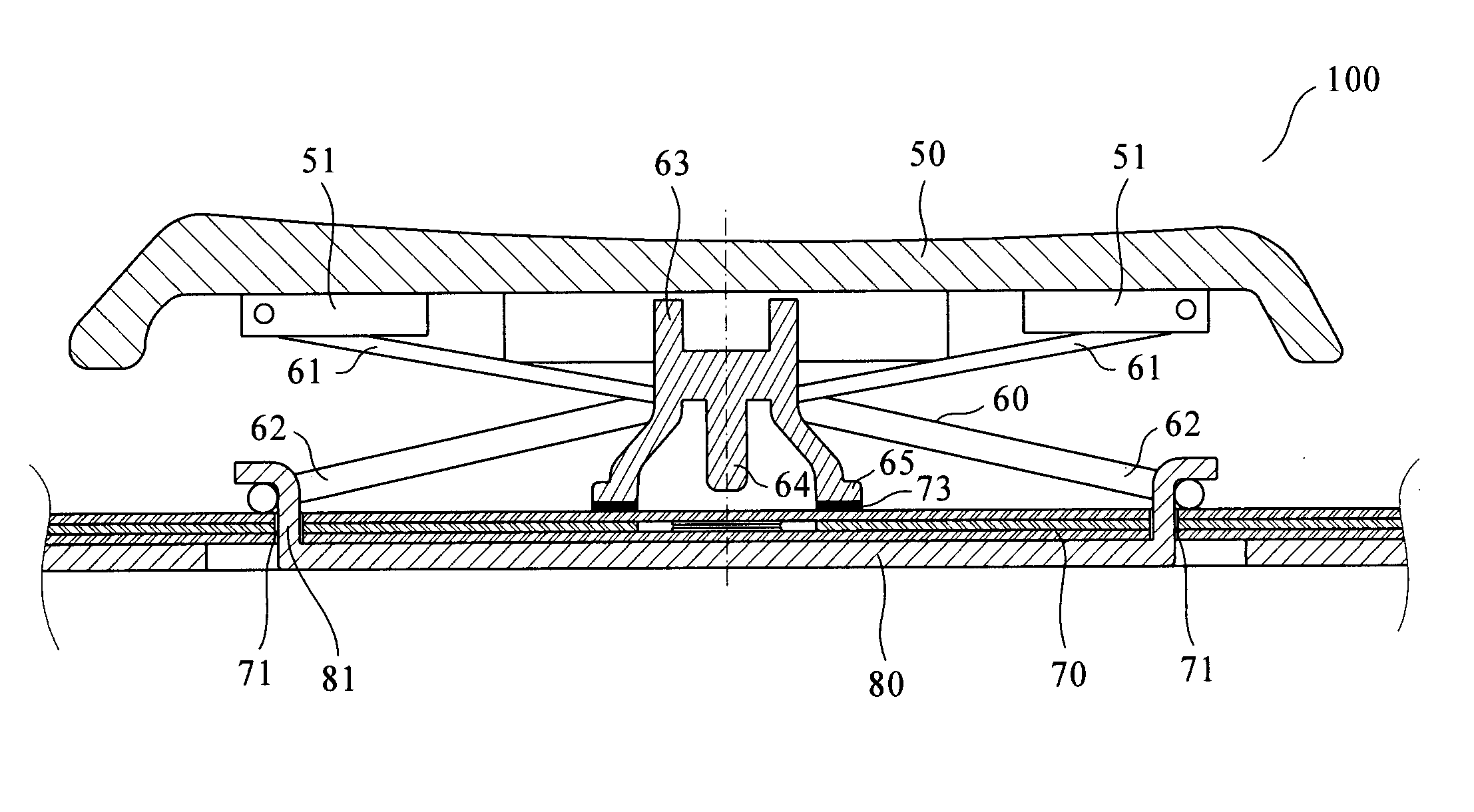
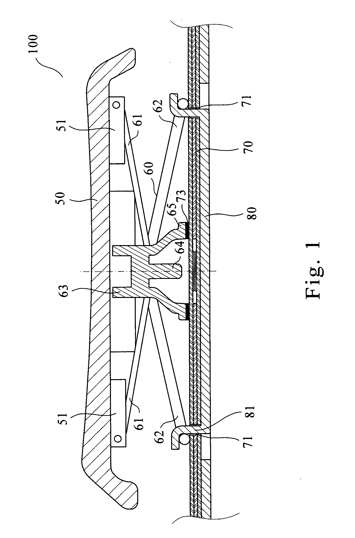
[0023] Please refer to FIG. 1, which shows a side sectional view of the key structure 100 of the present invention. The key structure 100 of the present invention comprises: a key cap 50, with an upper fixing portion 51 disposed on each of the two sides of the lower portion thereof; a scissor-type frame 60, disposed with a pair of upper pivot joint portions 61 and a pair of lower pivot joint portions 62; an elastic contact body 63, provided with a contact portion 64 and a plurality of flanges 65 on the bottom surface thereof; a membrane circuit board 70, made of a triple-layered circuit board composed of an upper layer, a middle layer and a lower layer, with a pair of through holes 71 passing through the membrane circuit board 70; and a bottom board 80, provided with a pair of lower fixing portions 81 corresponding to the upper fixing portions 51.

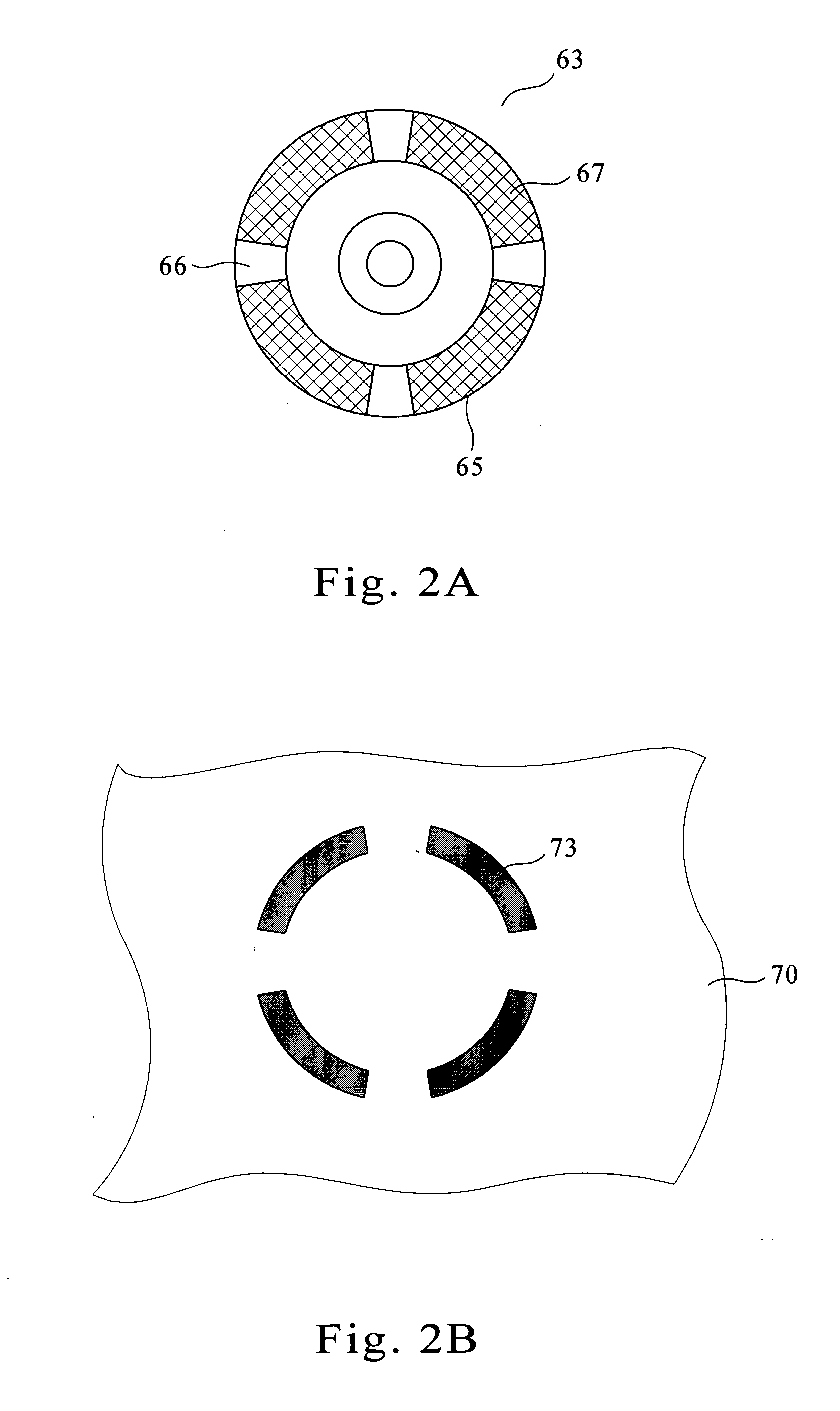
[0024] Please refer to FIG. 2A, which shows a bottom view of the elastic contact body 63 of the key structure 100 of the present inventio...

second embodiment

[0027] Please refer to FIG. 4 with reference to FIG. 3B again, FIG. 4 shows a side sectional view of the elastic contact body 63 and the membrane circuit board 70 bonding together of the present invention. By the height difference between the print layer 72 and the membrane circuit board 70 and a plurality of discontinuous printing portions 72 to form the holes 74, the press force caused by pressing the key can be released via the holes 74. Hence, it is not necessary to form additional holes on the elastic contact body 63. Furthermore, the embossed surface 67 of the bottom of the elastic contact body 63 increases the surface area to securely accommodate the adhesive 73 to enhance bondability between the elastic contact body 63 and the membrane circuit board 70, and preventing the adhesive 73 from being extruded out from therebetween.


PUM


Abstract

A key structure is provided. The present key structure includes a key cap, a scissor-type frame, an elastic contact body, a membrane circuit board, and a bottom board. A plurality of flanges is provided on the bottom of the elastic contact body, with the surface of the flange being formed as an embossed surface having a cross-striped structure. A print layer is provided on the area of the membrane circuit board corresponding to the flanges of the bottom of the elastic contact body, such that there is a height difference between the print layer and the membrane circuit board. The print layer is formed of a plurality of discontinuous printing portions between which a plurality of holes is formed. After the elastic contact body is bonded to the membrane circuit board by an adhesive, the press force of the elastic contact body caused by pressing the key can be released via the holes. The bonding area of the bottom of the elastic contact body is increased by the cross-striped structure of the embossed surface so as to enhance bonding between the elastic contact body and the membrane circuit board and prevent the adhesive from being extruded out from therebetween.

Description

BACKGROUND OF THE INVENTION [0001] 1. Field of the Invention [0002] The present invention relates to a key structure, and more particularly, to a key structure with an elastic contact body having a bottom surface formed as an embossed surface provided with a cross-striped structure. The bonding area of the bottom surface of the elastic contact body is increased by the cross-striped structure so as to enhance bonding between the elastic contact body and a membrane circuit board and prevent the adhesive from being extruded out from therebetween, when assembling components of the key structure. [0003] 2. Description of the Related Art [0004] Conventionally, the elastic contact body of the key structure is placed between a key cap and a circuit board. By pressing the key cap, the elastic contact body is caused to press the conductive membrane on the circuit board such that the messages or commands ordered by pressing the keys are transmitted to a display. A conventional keyboard is prov...

Claims


Application Information

Patent Timeline
IPC IPC(8): H01H13/85
CPCH01H13/85H01H2215/012H01H2215/006H01H2213/002
Inventor TSAI, CHING CHENG
Owner CHICONY ELECTRONICS
Why Eureka
Try Eureka