Method of manufacturing hot formed object, and device and method for continous high-frequency heating

a manufacturing method and high-frequency heating technology, applied in dielectric heating circuits, baking ovens, cooking vessels, etc., can solve the problems of shortening the molding time of conventional external heating methods, and affecting the production efficiency of hot-formed objects. , to achieve the effect of preventing malfunctioning detection of sparks, preventing high frequency, and preventing damag

Inactive Publication Date: 2005-05-12
NISSEI KK +1
View PDF11 Cites 4 Cited by
  • Summary
  • Abstract
  • Description
  • Claims
  • Application Information

AI Technical Summary

Benefits of technology

[0052] According to the above method, it is possible to prevent high frequency from flowing between the spark-sensing parts connected on the circuit, and to prevent an arc at the moment when the spark-...

Problems solved by technology

If there is any electrification between the feeder electrode and the grounding electrode to be insulated from each other, a spark is generated between the electrodes, which cause problems of damage to the electrodes or a scorch on the objects to be heated.
However, the conventional external heating method needs a long molding time with less production efficiency.
It also causes uneven baking and thereby uneven molded articles due to unequal temperature inside or between molds.
However, this method is ineffective for objects of relatively small size and relatively low unit cost, as the above molded articles.
Whereas in the art (B), for example, making a large-scale manufacturing equipment for improving production efficiency practically causes problems of generation of a spark, dielectric breakdown and an arc, as mentioned below.
First, in the art (B), when high frequency is applied to the entire heating zone B, localization of high frequency is found on part of the heating zone B. Therefore, if a manufacturing apparatus becomes larger, concentration of high-frequency energy is generated due to the localization of high frequency, thereby giving problems such as overheating of the raw materials wherein high frequency is localized, a spark or dielectric breakdown between the metal molds 7 (electrodes) in the localized area, as well as generation of a spark at the po...

Method used


Image

  • Method of manufacturing hot formed object, and device and method for continous high-frequency heating
  • Method of manufacturing hot formed object, and device and method for continous high-frequency heating
  • Method of manufacturing hot formed object, and device and method for continous high-frequency heating

Examples


embodiment 1

[0110] An embodiment of the present invention is explained below referring to FIG. 1 to FIG. 13. However, the present invention is not limited to this embodiment.

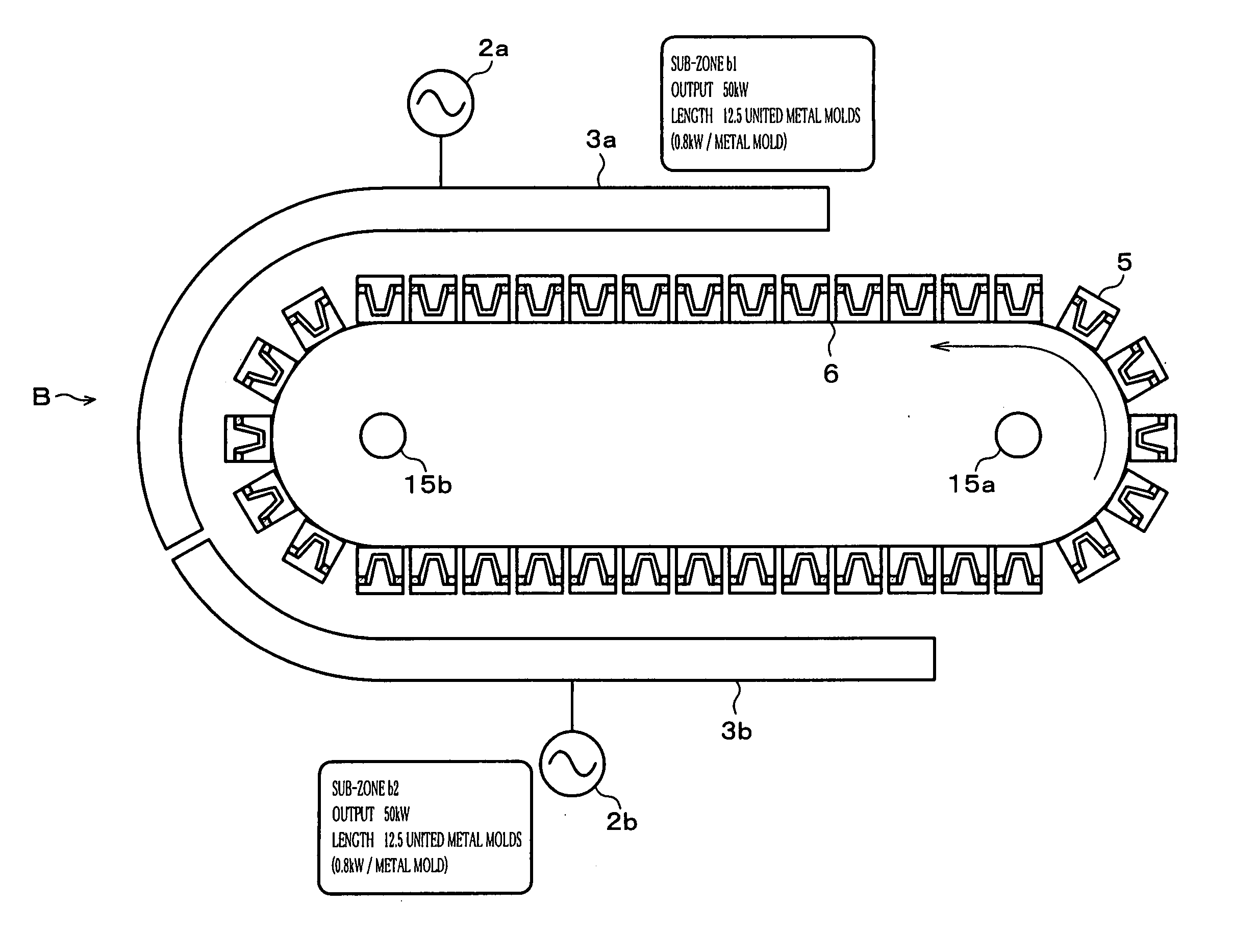
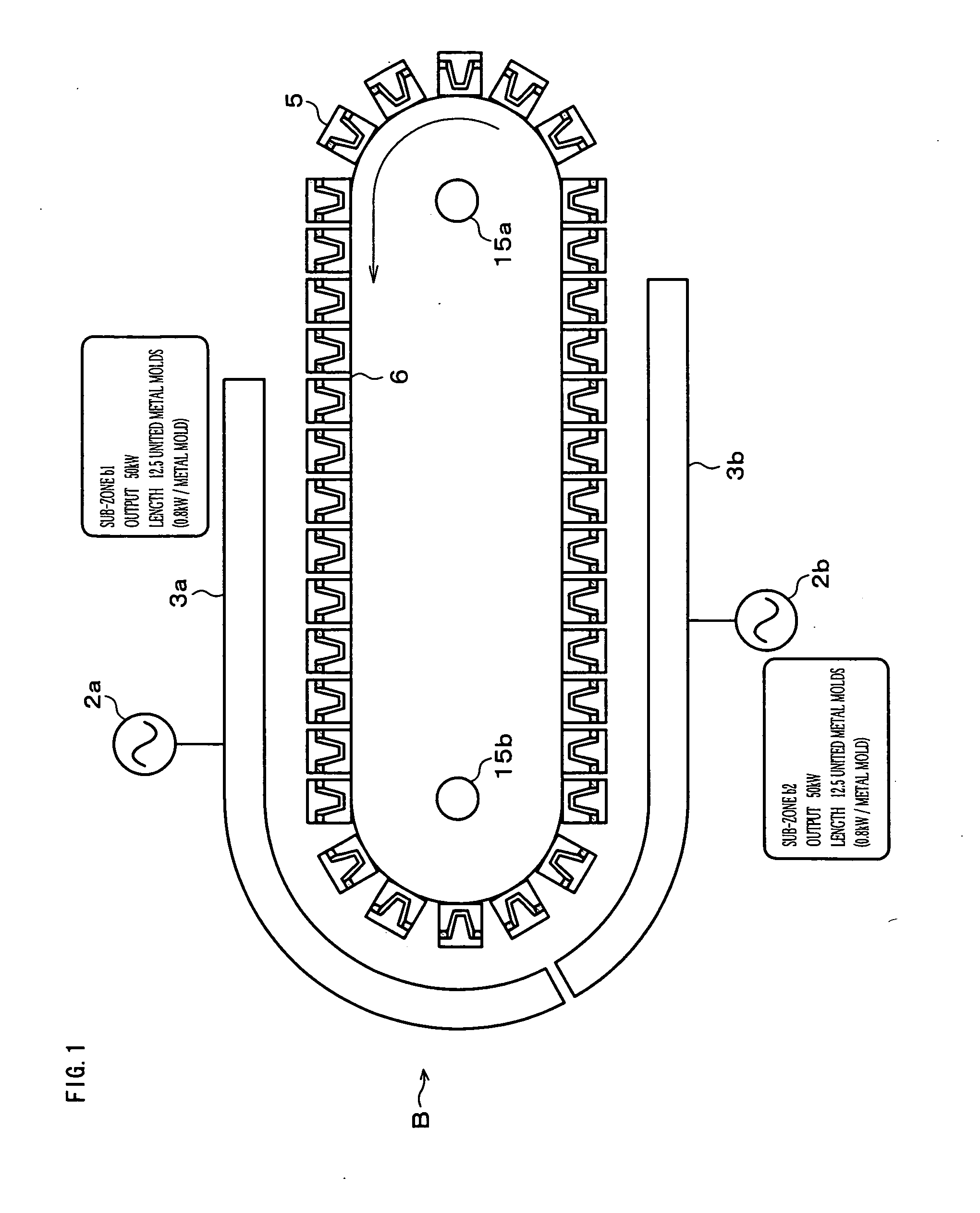
[0111] In a method for manufacturing heated and molded articles in accordance with the present invention, continuously transferring the molds wherein raw materials for molding are placed, passing through an area where high-frequency alternating current is applied (heating zone), and heating and molding the raw materials by generating dielectric heating, in particular, the heating zone is divided into sub-zones, each of which has a power source section (an oscillator).

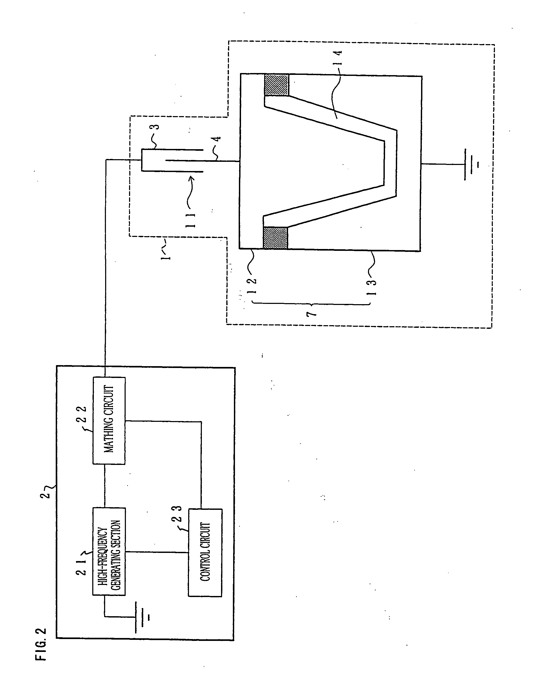
[0112] Also, in a continuous high-frequency heating apparatus in accordance with the present invention, continuously transferring objects to be heated with electrodes, passing through an area where high-frequency alternating current is applied (heating zone), and generating dielectric heating on the objects, this heating zone is divided into sub-zones, each o...

embodiment 2

[0194] The following description explains another embodiment of the present invention referring to FIG. 14 to FIG. 16, but the present invention is not limited to this embodiment. For convenience, the same numbers are shown for the members having the same function as the members used in the above embodiment 1, with the explanation left out.

[0195] In the above embodiment 1, the heating zone B is divided into two. In this embodiment, the heating zone B is divided into more than three.

[0196] More specifically, for example, as shown in FIG. 14, the heating zone B is divided into five sub-zones, b1, b2, b3, b4 and b5 from the previous part based on the moving direction of the conveyer 6. Each of the sub-zones has power source sections 2a, 2b, 2c, 2d, and 2e as well as a power feeding sections 3a, 3b, 3c, 3d, and 3e, respectively.

[0197] A way to divide the heating zone B, that is, a length of each of the sub-zones (length from the power feeding sections 3a to 3e) or a high-frequency ou...

embodiment 3

[0210] Still another embodiment of the present invention is described below referring to FIG. 17 and FIG. 18 as well as FIG. 26 and FIG. 27. The present invention is not limited to this embodiment. For convenience of explanation, the same numbers are shown for the members having the same function as the members used in the above embodiments 1 and 2 with the explanation left out.

[0211] In the above embodiments 1 and 2, even if the heating zone B is divided into sub-zones, both dielectric heating through the high-frequency heating means and external heating through the external heating means are used in the entire heating zone B. This embodiment includes an area where external heating is only performed, by providing a high-frequency application suspension zone where no high-frequency alternating current is applied, in part of the heating zone B.

[0212] More specifically, in this embodiment, as shown in FIG. 17, the heating zone B is basically divided into five sub-zones explained in ...


PUM

PropertyMeasurementUnit
Volumeaaaaaaaaaa
Volumeaaaaaaaaaa
Volumeaaaaaaaaaa

Abstract

Raw materials are portioned in a plurality of molds, which are continuously moved and transferred to a heating area by a conveyer. The heating area is divided into a plurality of sub-areas, each of which has power source means and power feeding means. The raw materials are heated and molded by applying high frequency to the molds from the power feeding means. Even if the heating apparatus is large, it is possible to restrain or prevent concentration of high-frequency energy since the heating area is divided into sub-areas.

Description

TECHNICAL FIELD [0001] The present invention relates to a method for manufacturing heated and molded articles by heating raw materials fed in molds, especially a method for manufacturing heated and molded articles, including a process for dielectrically heating raw materials by applying high-frequency alternating current to molds. In addition, the present invention relates to an apparatus and a method for high-frequency heating to heat objects placed between electrodes by applying high-frequency alternating current, especially a continuous dielectric heating apparatus and a continuous high-frequency heating method, wherein the objects can be dielectrically heated by applying high-frequency alternating current to the continuously moving electrodes with no contact, for example, which can be desirably used as a method for manufacturing the heated and molded articles. BACKGROUND ART [0002] A high-frequency heating method has been known as an art capable of effectively performing heat tr...

Claims


Application Information

Patent Timeline
IPC IPC(8): A21C15/02A23G3/02A23L3/01A23L3/365B29C31/04B29C33/36B29C35/02B29C35/12B29C39/06B29C39/38H05B6/50H05B6/52H05B6/54H05B6/60
CPCA21C15/025A23G3/0252A23L3/01A23L3/365B29C31/047B29C33/36H05B6/60B29C35/12B29C43/06B29C43/52B29C44/388B29K2995/0059B29K2995/006B29C35/0277
Inventor TAMURA, TOMOYAOKUDA, NAOYUKIOTANI, YOSHIYUKIKOSAKA, TSUTOMUSHINOMIYA, YASUOHARUTA, TOSHITAKAKARASAWA, TAIZOAKESAKA, YOSHIOYANAGITANI, MASATONAGATA, TSUNEOYAMAMOTO, YASUJI
Owner NISSEI KK
Why Eureka
Try Eureka