Handheld gyroscopic exercise device
- Summary
- Abstract
- Description
- Claims
- Application Information
AI Technical Summary
Benefits of technology
Problems solved by technology
Method used
Image
Examples
Embodiment Construction
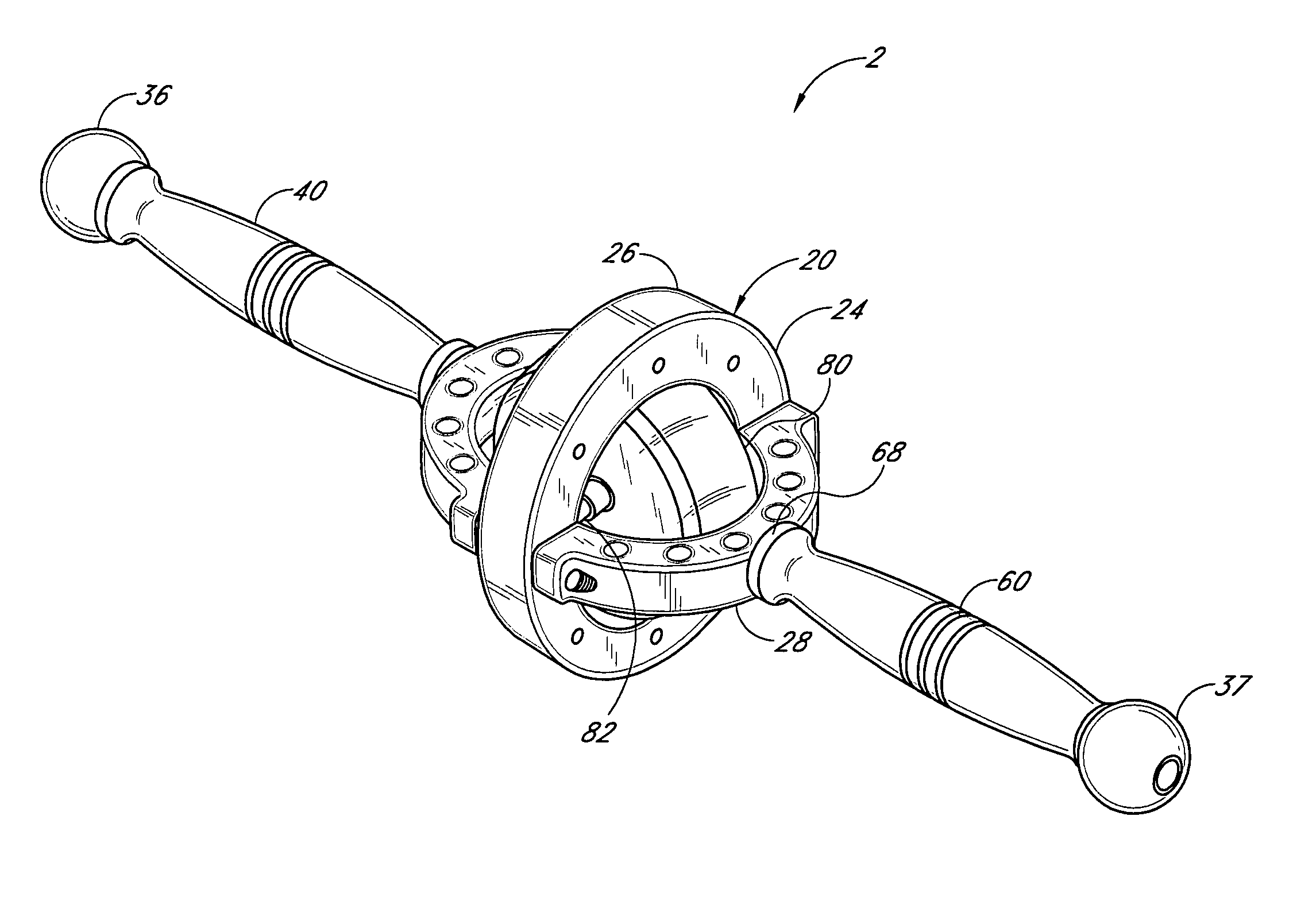
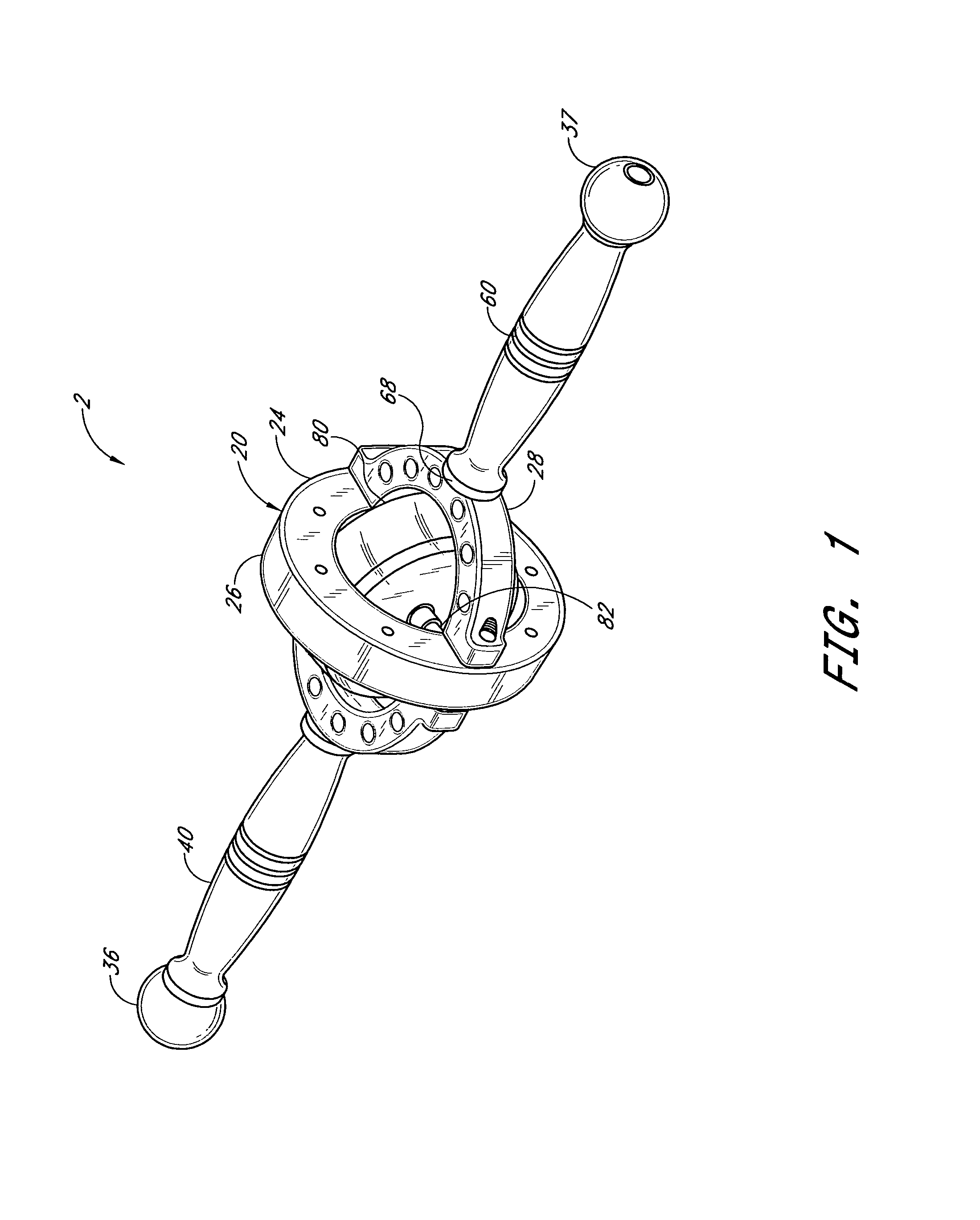
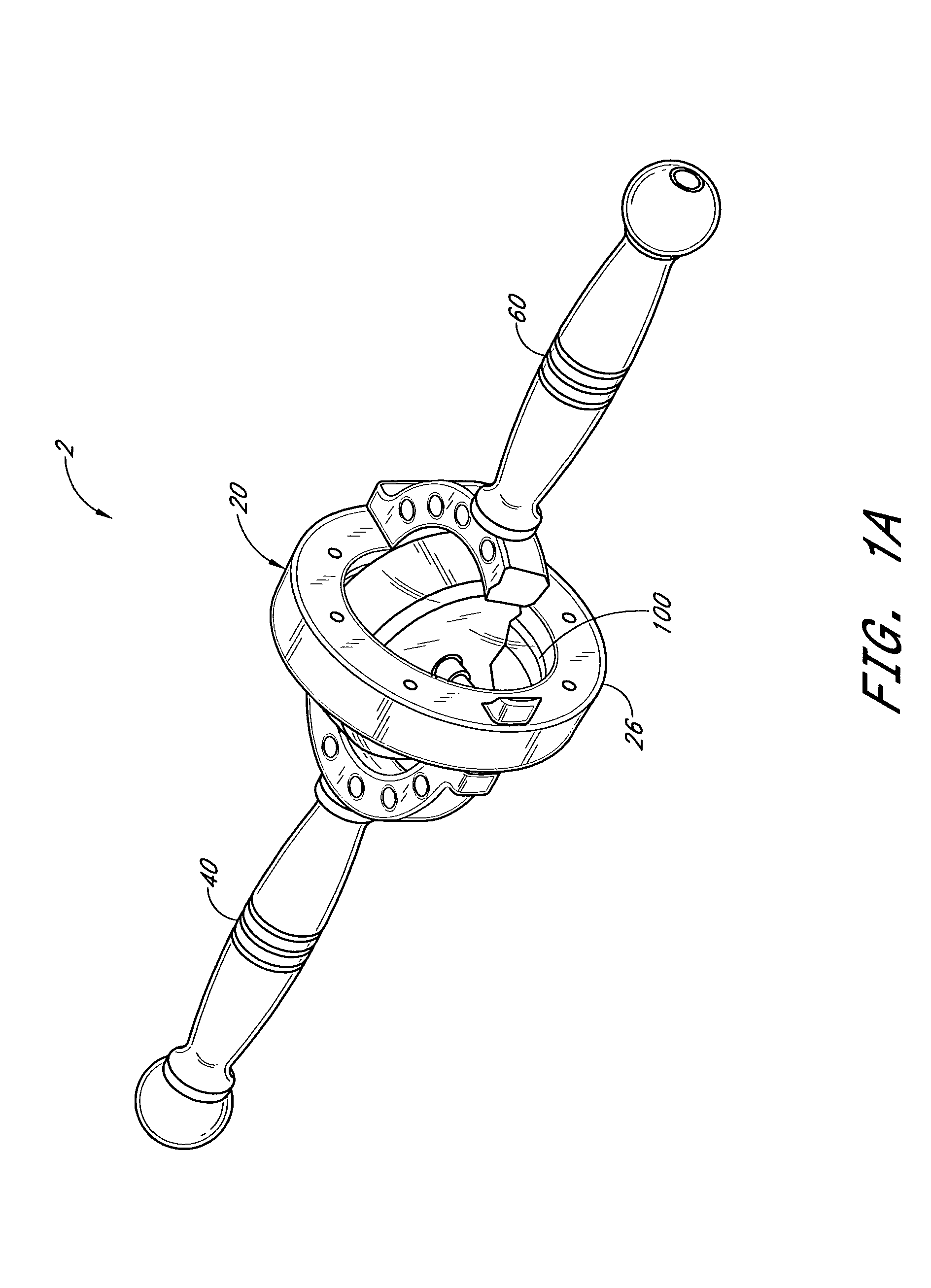
[0035]FIG. 1 is perspective view of a gyroscopic exercise device 2 incorporating the invention. The gyroscopic exercise device 2 illustrated comprises a housing 20 having a frame 24 formed by a pair of rigid rings 26 and 28 that generally define planes that are perpendicular to each other. A pair of handles 40 and 60 are attached to opposite sides of the ring 28. A wheel or rotor 80 is coupled to a shaft 82, which is rotatably coupled to a ring guide 100 and the housing 20. More specifically, the ends of shaft 82 are rotatably mounted in the ring guide 100 (as shown in FIG. 1A) which includes a ring shape periphery and is mounted within the ring 26. The ring guide 100 in effect captures the ends of the shaft 82 while permitting them to rotate about the shaft axis; but at the same time the ring guide 100 can rotate within the ring 26 in a plane perpendicular to an axis 104 that extends through the handles 40 and 60.
[0036] As seen in the cross-sectional view of the gyroscopic exercis...
PUM
 Abstract
Description
Claims
Application Information
 - R&D
- Intellectual Property
- Life Sciences
- Materials
- Tech Scout
- Unparalleled Data Quality
- Higher Quality Content
- 60% Fewer Hallucinations
Browse by: Latest US Patents, China's latest patents, Technical Efficacy Thesaurus, Application Domain, Technology Topic, Popular Technical Reports.
© 2025 PatSnap. All rights reserved.Legal|Privacy policy|Modern Slavery Act Transparency Statement|Sitemap|About US| Contact US: help@patsnap.com


