
Leg rest and kneeler assembly for a medical examination table

a technology for kneelers and examination tables, which is applied in the direction of tables, surgery, nursing beds, etc., can solve the problems of reducing affecting the overall effectiveness of the assembly, and unable to allow smooth movement between different positions, so as to achieve simple and efficient design, extend the length of the available table surface, and reduce the effect of assembly labor

Inactive Publication Date: 2005-05-19
THE BREWER
View PDF99 Cites 14 Cited by
  • Summary
  • Abstract
  • Description
  • Claims
  • Application Information

AI Technical Summary

Benefits of technology

"The present invention is a leg rest extension assembly for use on an examination table or chair. The assembly can be extended outward from the table surface to increase the length of the available table surface. The assembly includes a frame and an extension section that is slidably connected to the frame within a guide rail. The assembly can be locked in predetermined extended positions. The assembly can also be used as a kneeler or kneeing section, allowing the frame to be moved into any position between a vertical position and a horizontal position with respect to the examination table. The extension section can be positioned at different heights with respect to the frame, accommodating people of different heights. The guide rails are designed in an efficient manner so as not to require unnecessary bearing elements that may prevent smooth movement of the extension section."

Problems solved by technology

The footrests usually require the steps of adding or removing one or more attachments to accomplish positional movement, which can be burdensome.
Likewise, some designs that do not need the addition or removal of attachments do not allow for smooth movement between different positions.
However, the assembly has many interacting parts that do not always allow for the easiest transition from one position to another.
The indents provide a ratcheting action, which makes adjustment of the assembly tedious and also wears away the working parts over time, thereby diminishing the overall effectiveness of the assembly.
Also, the guide area used to adjust the vertical and horizontal sections of the assembly relative to one another is designed with at least one sharp right angle, which does not provide for easy sliding movement of the relative sections of the assembly.

Method used


Image

  • Leg rest and kneeler assembly for a medical examination table
  • Leg rest and kneeler assembly for a medical examination table
  • Leg rest and kneeler assembly for a medical examination table

Examples


Embodiment Construction

[0027] Although the disclosure hereof is detailed and exact to enable those skilled in the art to practice the invention, the physical embodiments herein disclosed merely exemplify the invention which may be embodied in other specific structure. While the preferred embodiment has been described, the details may be changed without departing from the invention.

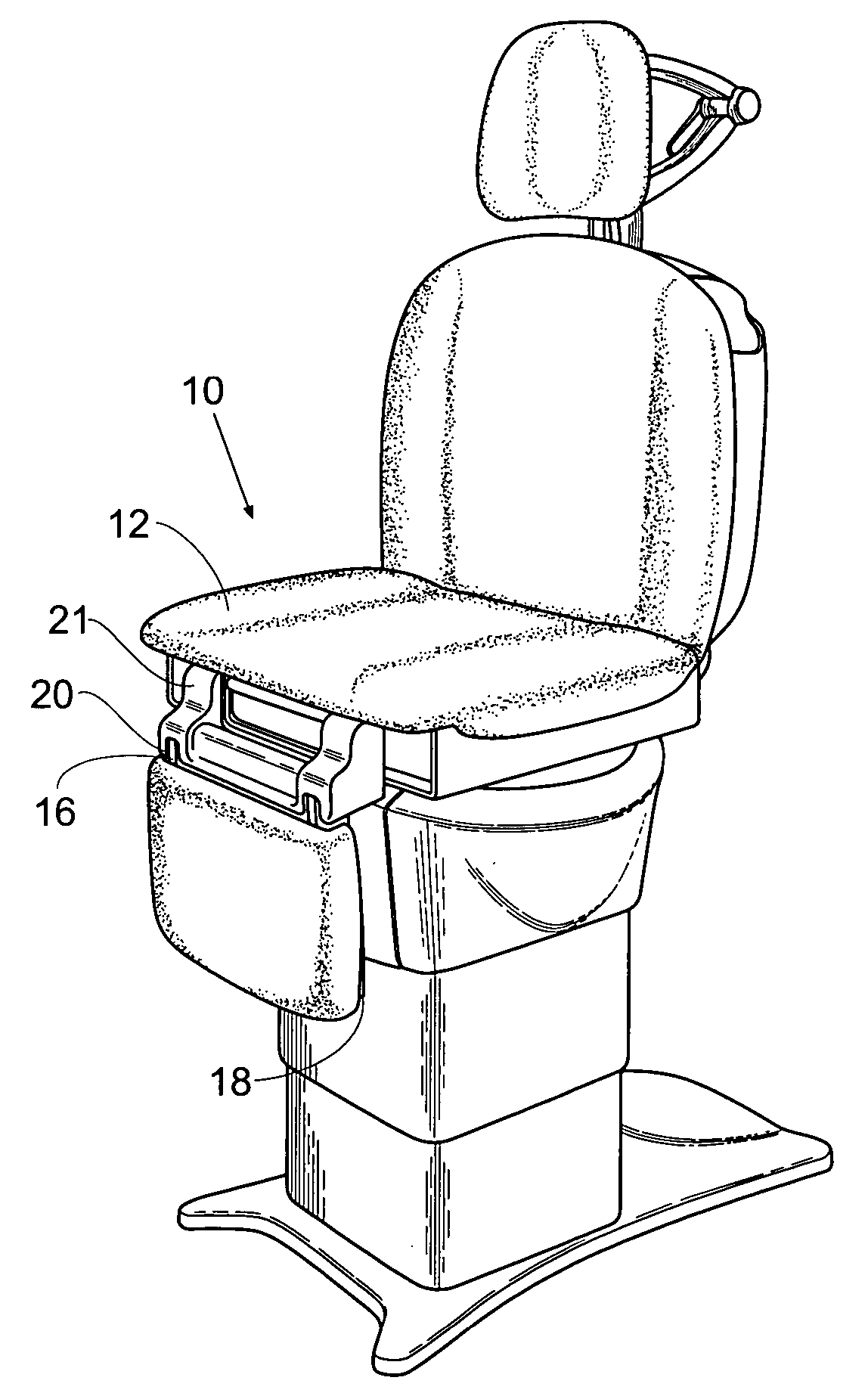
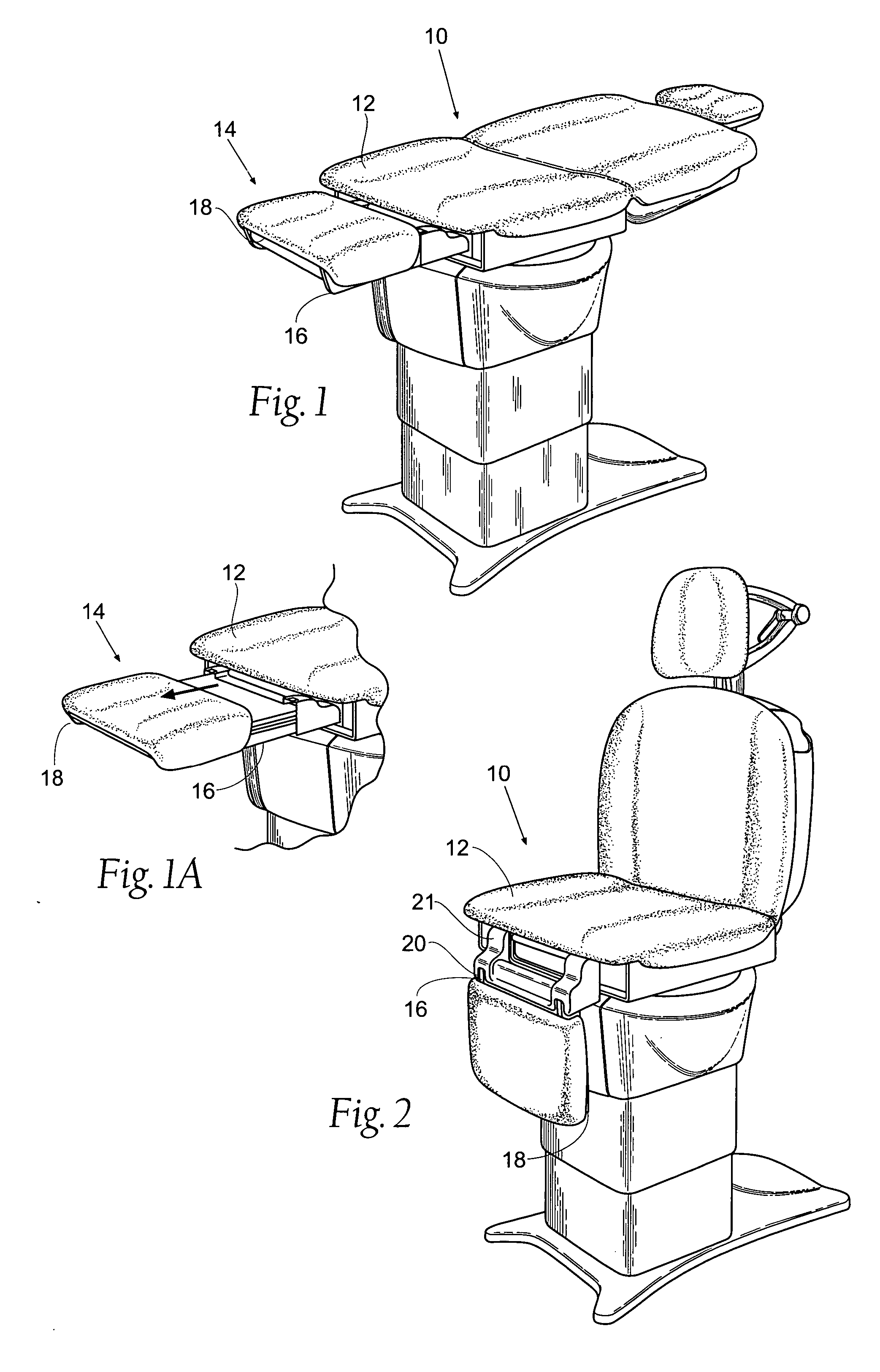
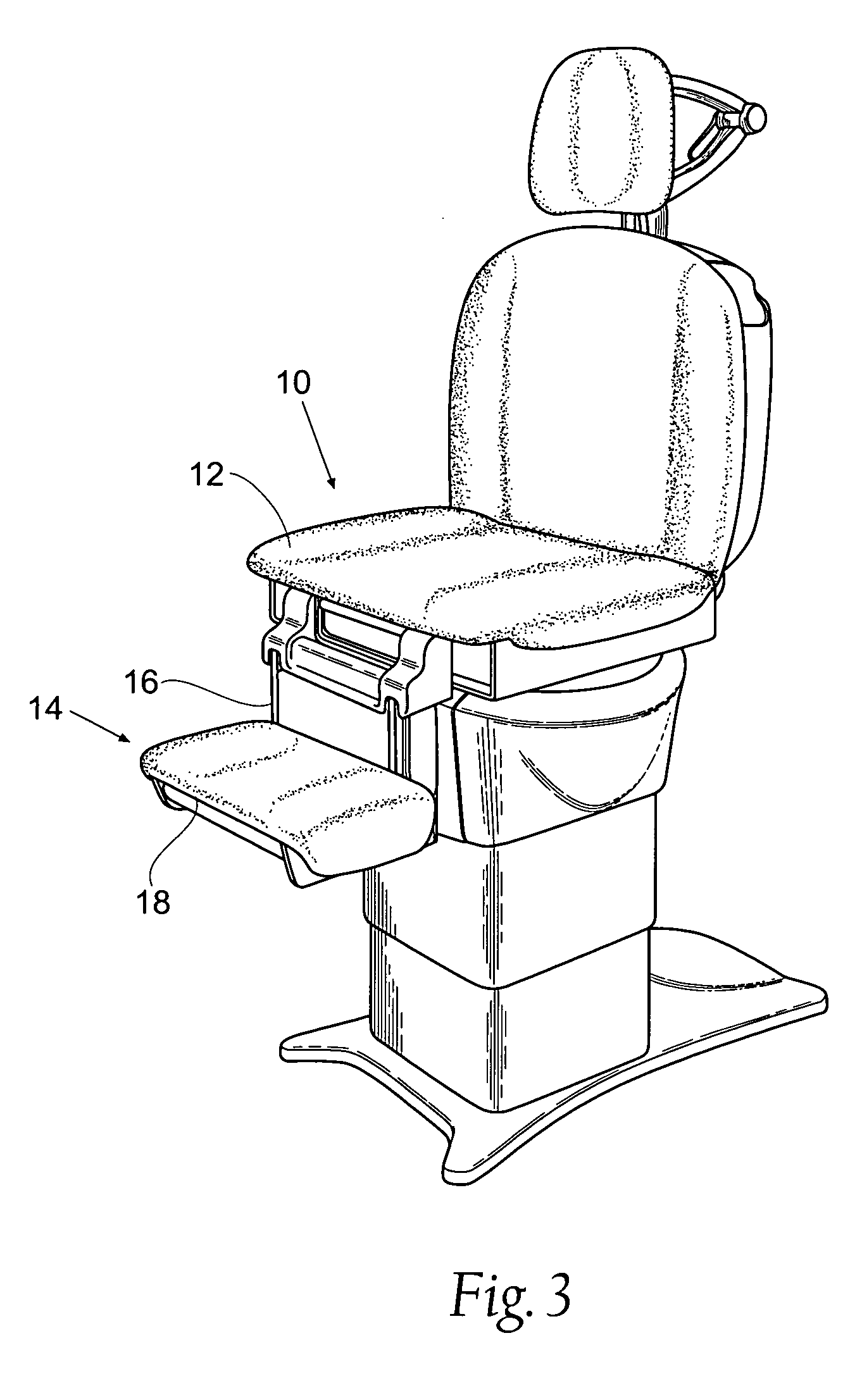
[0028]FIG. 1 is a perspective view of a stationary support 10 including a support surface 12 and a leg rest assembly 14. For clarity the stationary support 10 will be referred to as a table, but it is understood that the present invention could be used in connection with a chair, table, bed, or similar piece of furniture. The leg rest assembly 14 allows for the table 10 to be adjusted into a wide range of sitting, kneeling, and lying positions. The leg rest assembly 14 has two main sections, a frame 16 and an extension section 18. The frame 16 can include any structure that will provide a support base for further movement of th...


PUM


Abstract

A leg rest assembly for an examination table that is adaptable to extend the length of the table or to act as a kneeler section is disclosed. The extension section of the assembly has an efficient design that allows for the assembly to be easily changed from an extension section to a kneeler. A latching mechanism to hold the assembly in an extended position outwardly from the table is designed separately from the guide mechanism that move the assembly into a kneeler configuration.

Description

RELATED APPLICATION [0001] This application claims the benefit of co-pending Provisional Patent Application Ser. No. 60 / 506,989, filed Sep. 29, 2003.BACKGROUND OF THE INVENTION [0002] The present invention relates to adjustable medical examination equipment and, more specifically, to an adjustable leg rest and kneeler assembly. [0003] Adjustable footrests and kneelers for medical examination chairs and tables are well known in the art, but generally are elaborate in design or do not change from one position to another easily. The footrests usually require the steps of adding or removing one or more attachments to accomplish positional movement, which can be burdensome. Likewise, some designs that do not need the addition or removal of attachments do not allow for smooth movement between different positions. [0004] For instance U.S. Pat. No. 4,958,816 discloses a leg and foot support assembly that is adjusts into different positions. However, the assembly has many interacting parts t...

Claims


Application Information

Patent Timeline
Patent Type & Authority Applications(United States)
IPC IPC(8): A61G7/015A61G13/00A61G13/12A61G15/00A61G15/12
CPCA61G13/0018A61G13/12A61G13/1245A61G2200/38A61G15/00A61G15/12A61G2200/34A61G13/125
Inventor JACOBS, JERRY J.DEBRAAL, JACK A.JENSEN, MARK E.
Owner THE BREWER
Learn More