
Stirling engine and hybrid system that uses the stirling engine

Inactive Publication Date: 2005-05-19
TOYOTA JIDOSHA KK
View PDF7 Cites 7 Cited by
  • Summary
  • Abstract
  • Description
  • Claims
  • Application Information

AI Technical Summary

Benefits of technology

[0014] It is an object of the present invention to provide a compact and effective Stirling engine.

Problems solved by technology

An increase in the volume of the heat exchanger results in a decrease in output of the Stirling engine.
However, a compact heat exchanger does not perform the heat-exchange effectively.
However, if such Stirling engine is installed under environments in which it is difficult to ensure sufficient heat, it becomes necessary to efficiently use the available heat.
When the exhaust gas is used to heat the Stirling engine, the place where the Stirling engine can be installed becomes limited.
However, because of the V-shape, the Stirling engine becomes bulky and requires more space for installing.
Furthermore, the low-temperature cylinder and the radiator are connected to each other at almost a right angle, which is a disadvantage in a channel resistance (flow loss) of the working fluid.
In these Stirling engines, no countermeasures have been taken to efficiently use heat under environments in which it is difficult to ensure sufficient heat.
There is also a problem on the channel resistance of the working fluid.

Method used


Image

  • Stirling engine and hybrid system that uses the stirling engine
  • Stirling engine and hybrid system that uses the stirling engine
  • Stirling engine and hybrid system that uses the stirling engine

Examples


first embodiment

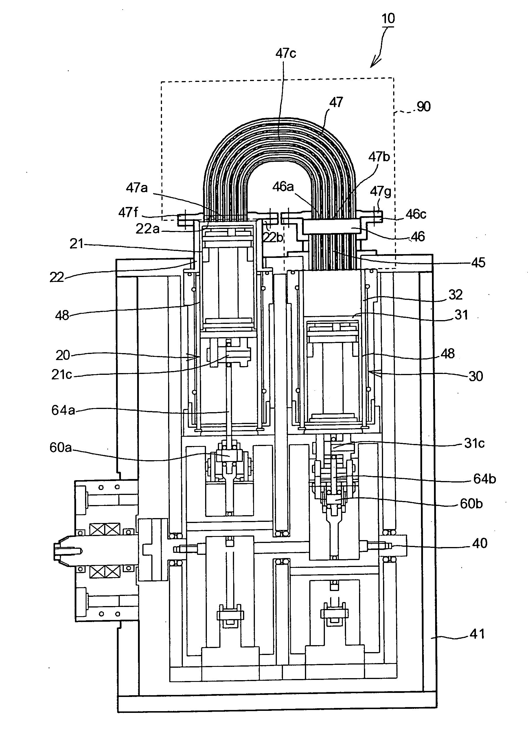
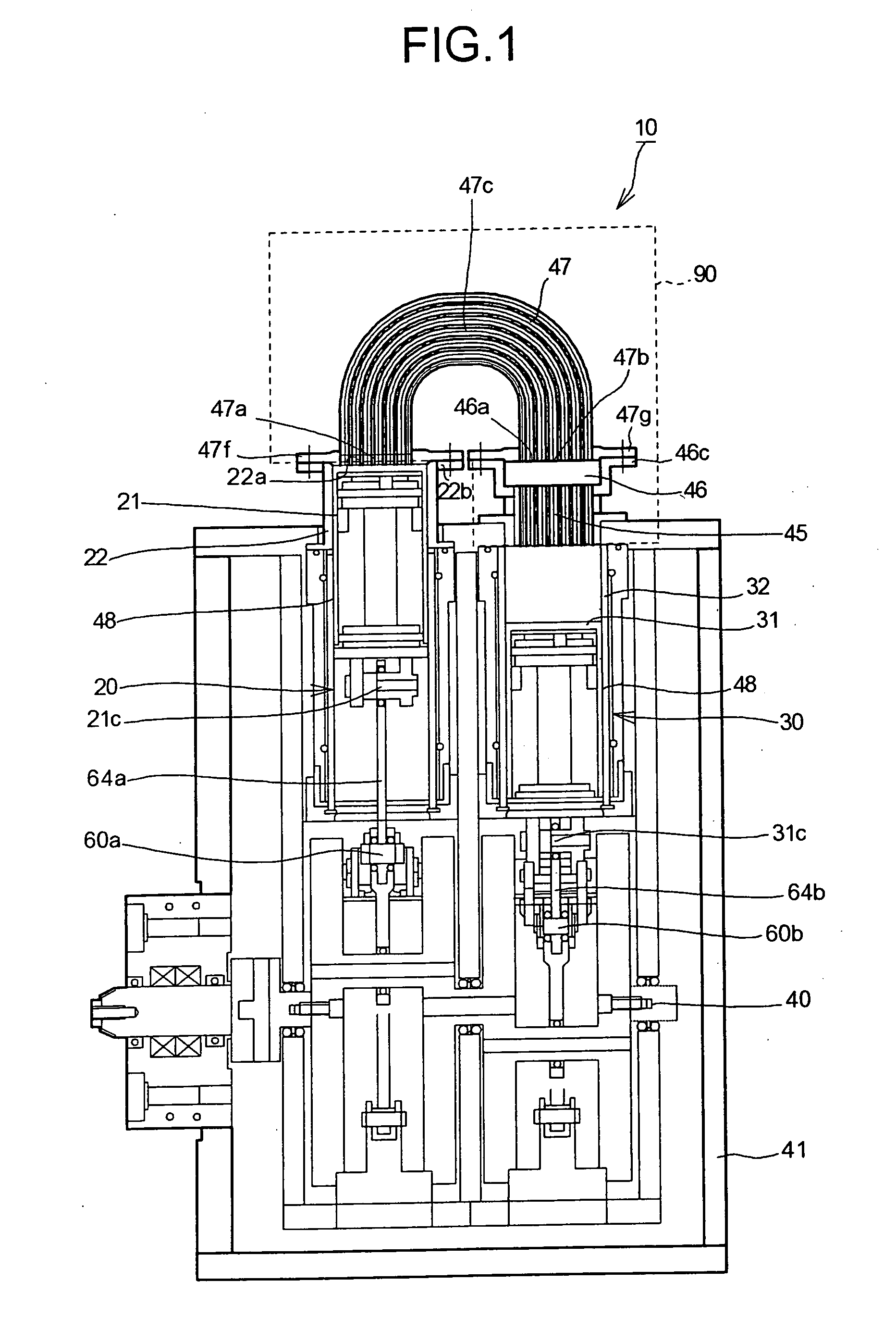
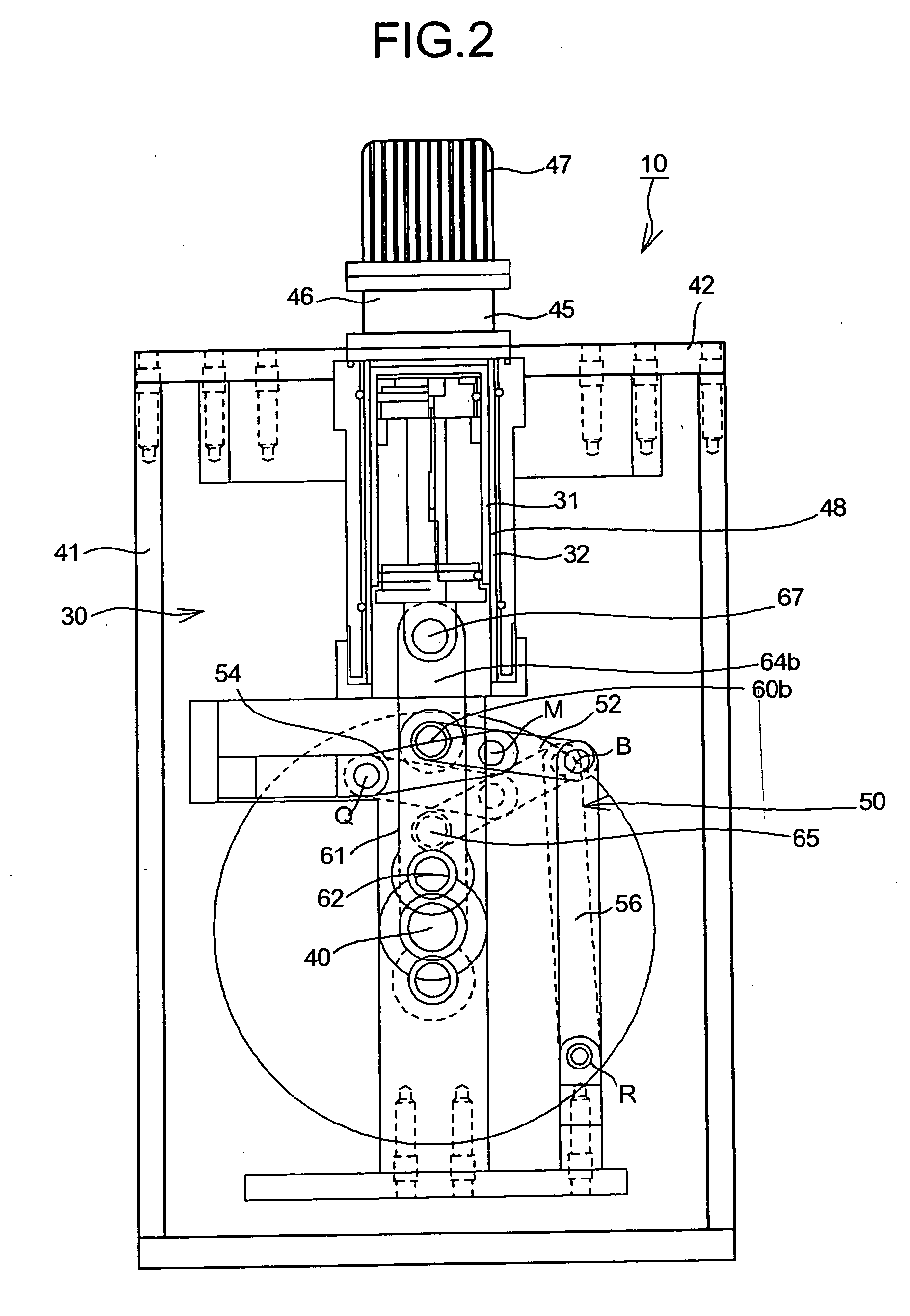
[0050]FIG. 1 is a front view of a Stirling engine according to the present invention. FIG. 2 is a side view of the Stirling engine. As shown in FIG. 1 and FIG. 2, a Stirling engine 10 is an α type (two-piston type) Stirling engine that has two power pistons 20 and 30. The two power pistons 20 and 30 are serially connected (through a heater) to and arranged in parallel with each other (hereinafter, “serial-parallel arrangement”). The power piston 30 is provided on a low temperature side (hereinafter, “low-temperature side power piston 30”), and the power piston 20 is provided on a high temperature side (hereinafter, “high-temperature side power piston 20”). A piston 31 (or a compression piston 31) of the low-temperature side power piston 30 is set to a phase difference so as to move with a delay by about 90 degrees at a crank angle with respect to a piston 21 (or an expansion piston 21) of the high-temperature side power piston 20.

[0051] Working fluid heated by a heater 47 flows into...

third embodiment

[0150] the present invention is explained below with reference to FIG. 20.

[0151] In the third embodiment, the same reference numerals as those in the first and the second embodiments are used. The detailed explanation is omitted and only a different point in terms of contents is explained below.

[0152]FIG. 20 is a front view of a Stirling engine 10A according to the third embodiment. Cylinders 22A and 32A are provided in a serial-parallel arrangement. A heat exchanger 90A includes a radiator 45A, a regenerator 46A, and a heater 47A. At least a part of the heat exchanger 90A is formed in a curved shape so that the heat exchanger 90A connects between the two cylinders 22A and 32A. In the third embodiment, the positions of the top dead centers of an expansion piston 21A and a compression piston 31A are the same as each other.

[0153] In the third embodiment, even if the installation space is compact and the Stirling engine 10A is installed in a limited space, the degree of flexibility o...


PUM


Abstract

A Stirling engine includes at least a first cylinder and a second cylinder arranged in serial, and a heat exchanger. The heat exchanger includes a radiator, a regenerator, and a heater. At least a part of the heat exchanger is formed in a curved shape so as to connect between the first cylinder and the second cylinder. The heater is formed in a curved shape so as to connect between the first cylinder and the second cylinder. The radiator and the regenerator are linearly formed along the direction of extension of the cylinder.

Description

BACKGROUND OF THE INVENTION [0001] 1) Field of the Invention [0002] The present invention relates to a Stirling engine and a hybrid system that uses the Stirling engine. [0003] 2) Description of the Related Art [0004] Stirling engine is an external combustion engine, i.e., in the Stirling engine, a working fluid is heated from outside. The Stirling engines are advantageous over other engines. For example, they has high thermal efficiency. Moreover, in Stirling engines, various types of alternative energies can be effectively used as a heat source for heating the working liquid. For example, even the low temperature difference energies such as solar energy, geothermal energy, or exhaust heat can be used as a heat source, which allows for energy saving. [0005] Japanese Utility Model Application Laid-Open Publication (JP-U) No. H04-89836 discloses a conventional Stirling engine. This Stirling engine is shown in FIG. 21. In this Stirling engine, a high-temperature side cylinder 121 and ...

Claims


Application Information

Patent Timeline
IPC IPC(8): F02G1/043F02G1/044F01N5/02F02G1/055F02G5/00
CPCF02G1/055Y02E10/46F02G2254/50
Inventor YAGUCHI, HIROSHISAWADA, DAISAKU
Owner TOYOTA JIDOSHA KK
Learn More