
Stirling engine and hybrid system that uses the Stirling engine
a technology of stirling engine and hybrid system, which is applied in the direction of machines/engines, mechanical equipment, lighting and heating apparatus, etc., can solve the problems of compact heat exchanger not performing heat exchange effectively, reducing the output of stirling engine, and becoming necessary to efficiently use the available heat. achieve the effect of compact and effective stirling engin
- Summary
- Abstract
- Description
- Claims
- Application Information
AI Technical Summary
Benefits of technology
Problems solved by technology
Method used
Image

Examples
first embodiment
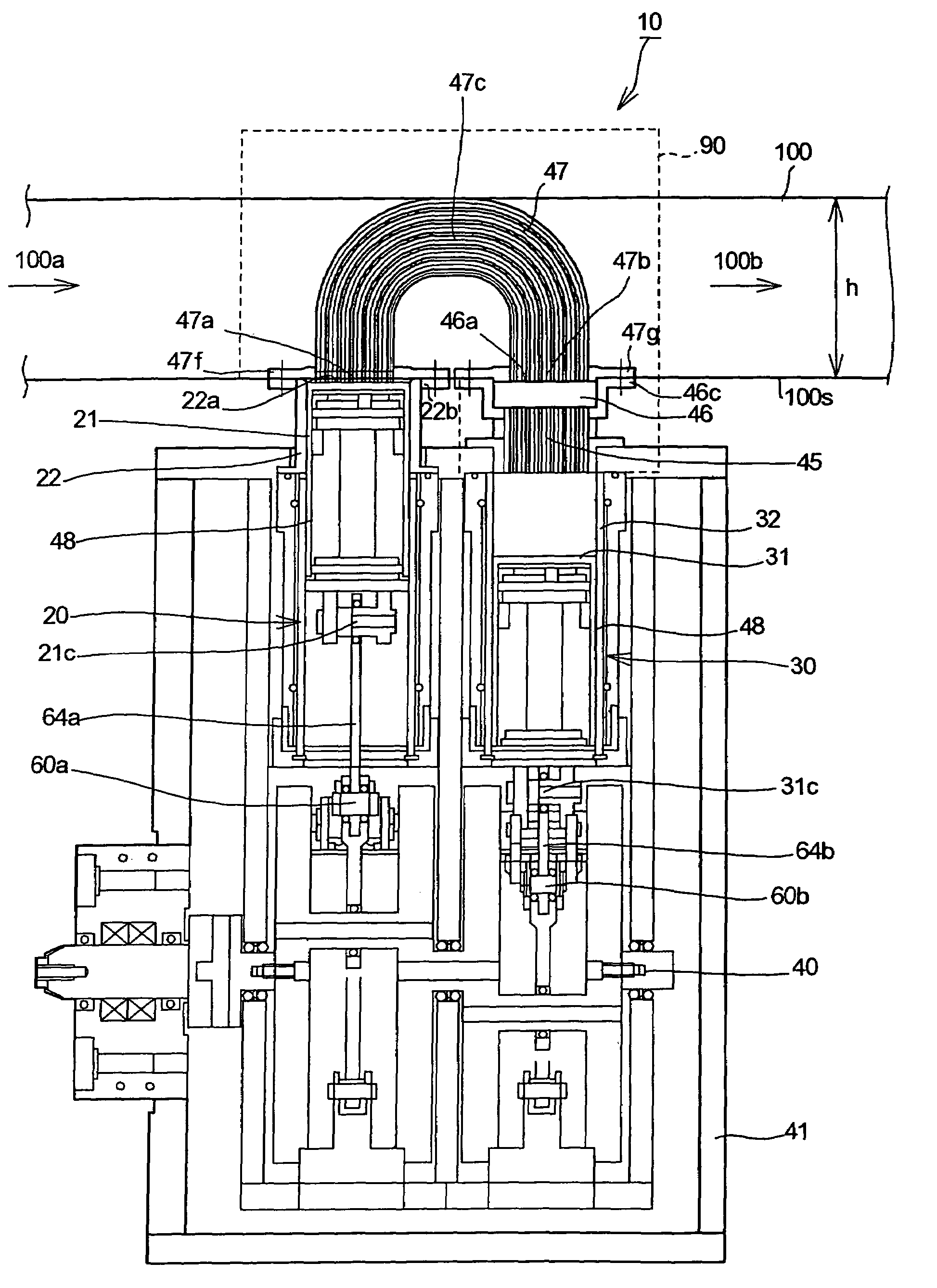
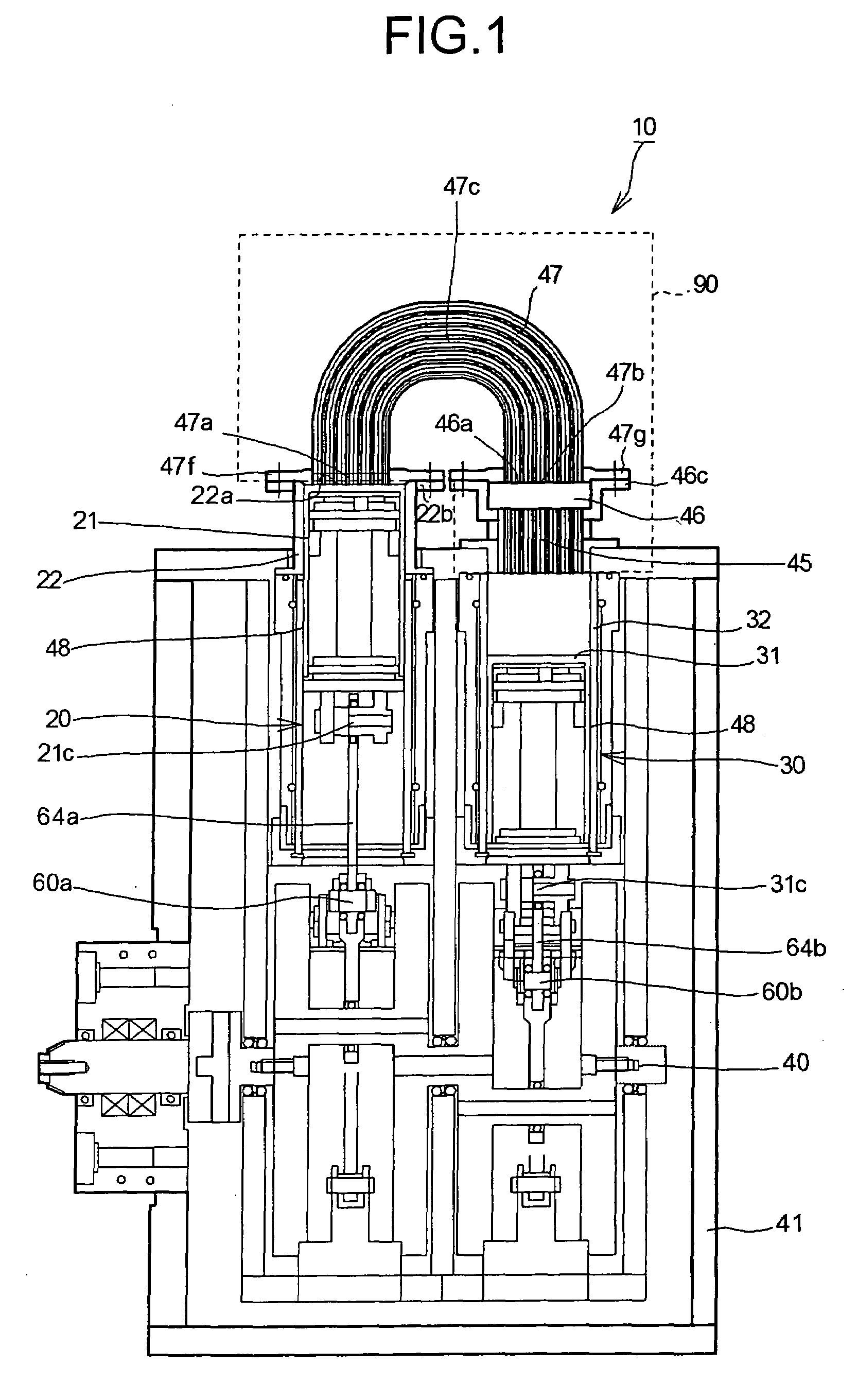
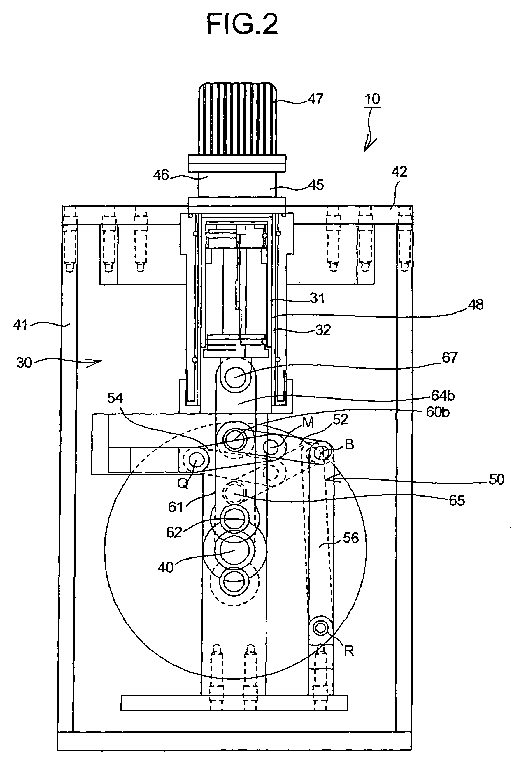
[0050]FIG. 1 is a front view of a Stirling engine according to the present invention. FIG. 2 is a side view of the Stirling engine. As shown in FIG. 1 and FIG. 2, a Stirling engine 10 is an α type (two-piston type) Stirling engine that has two power pistons 20 and 30. The two power pistons 20 and 30 are serially connected (through a heater) to and arranged in parallel with each other (hereinafter, “serial-parallel arrangement”). The power piston 30 is provided on a low temperature side (hereinafter, “low-temperature side power piston 30”), and the power piston 20 is provided on a high temperature side (hereinafter, “high-temperature side power piston 20”). A piston 31 (or a compression piston 31) of the low-temperature side power piston 30 is set to a phase difference so as to move with a delay by about 90 degrees at a crank angle with respect to a piston 21 (or an expansion piston 21) of the high-temperature side power piston 20.
[0051]Working fluid heated by a heater 47 flows into ...
third embodiment
[0150]the present invention is explained below with reference to FIG. 20.
[0151]In the third embodiment, the same reference numerals as those in the first and the second embodiments are used. The detailed explanation is omitted and only a different point in terms of contents is explained below.
[0152]FIG. 20 is a front view of a Stirling engine 10A according to the third embodiment. Cylinders 22A and 32A are provided in a serial-parallel arrangement. A heat exchanger 90A includes a radiator 45A, a regenerator 46A, and a heater 47A. At least a part of the heat exchanger 90A is formed in a curved shape so that the heat exchanger 90A connects between the two cylinders 22A and 32A. In the third embodiment, the positions of the top dead centers of an expansion piston 21A and a compression piston 31A are the same as each other.
[0153]In the third embodiment, even if the installation space is compact and the Stirling engine 10A is installed in a limited space, the degree of flexibility of ins...
PUM
 Abstract
Description
Claims
Application Information