Contact lens handling and inserting device and storage container

a technology for inserting devices and contact lenses, which is applied in the field of contact lens handling and inserting devices and storage containers, can solve the problems of introducing the possibility that the lens will become contaminated, affecting the use of the contact lens, and the user's grasping of the contact lens is much more difficul

Inactive Publication Date: 2005-05-19
VULCU EMIL +1
View PDF32 Cites 13 Cited by
  • Summary
  • Abstract
  • Description
  • Claims
  • Application Information

AI Technical Summary

Benefits of technology

[0012] The inserting and handling device includes a main body. A suction cup is located at a first end of the main body and has an opening that leads to and communicates with a hollow portion of the main body. According to a first embodiment of the inserting and handling device of the present invention, the main body has a deformable portion which allows a user to create a vacuum at the suction cup so as to permit the suction cup to grasp an object by the user deforming the deformable portion of the main body. In a second embodiment of the inserting and handling device of the present invention, a suction bulb is located on the main body and permits the creation of a vacuum in a channel in the

Problems solved by technology

This requires a user to remove the lens by hand and actually touch the lens, thereby introducing the possibility that the lens will become contaminated.
When the lens is put into a storage container, it is often difficult for th

Method used


Image

  • Contact lens handling and inserting device and storage container
  • Contact lens handling and inserting device and storage container

Examples


first embodiment

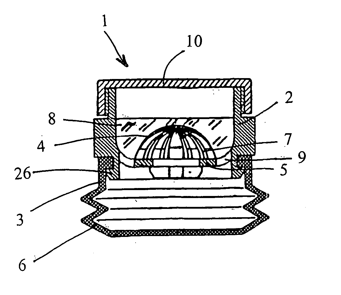
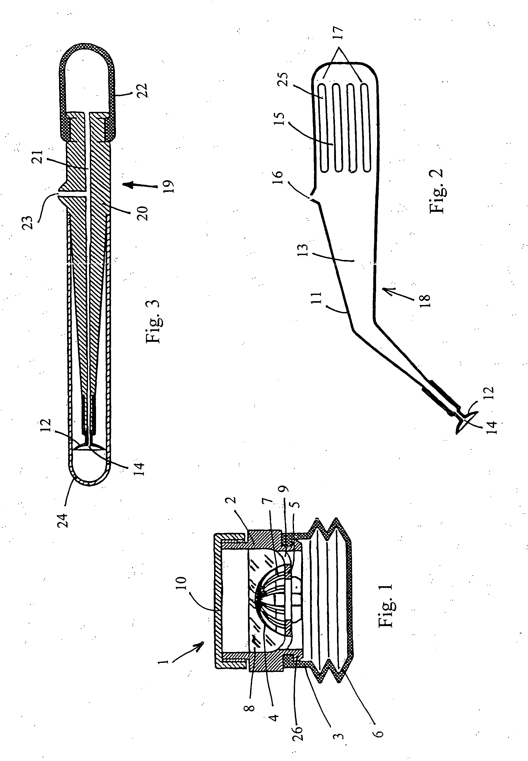
[0025] the inserting and handling device 18 as shown in FIG. 2 includes a main body which is hollow body 11. A suction cup 12 is located at a first end of the hollow body 11 and has an opening 14 that leads to and communicates with a hollow portion 13 of the hollow body 11. The suction cup is shown fitted onto one end of the hollow body 11. According to this embodiment of the inserting and handling device 18 of the present invention, the hollow body 11 has a deformable portion 15. This allows a user to create a vacuum at the suction cup 12 so as to permit the suction cup 12 to grasp an object such as a contact lens by deforming the deformable portion 15 of the hollow body 11 until air is discharged from the opening, and then applying a lesser force on the deformable portion 15 of the hollow body 11 such that a vacuum is formed in the hollow body 11. When a user places his finger over vacuum bleed hole 16 on the hollow body 11 of the device to seal the vacuum bleed hole 16, the user ...

second embodiment

[0029] the inserting and handling device 19 as shown in FIG. 3 includes a main body 20. A suction cup 12 is located at a first end of the main body 20 and has an opening 14 that leads to and communicates with an axial channel 21 which extends from a first end of the main body 20 to a second end of the main body 20. The suction cup 12 is shown fitted onto one end of the main body 20. According to this embodiment of the inserting and handling device 19 of the present invention, the hollow main body 20 has a bulb 22. The bulb 22 is flexible and can be formed from any known flexible material which is substantially airtight.

[0030] The bulb 22 allows a user to create a vacuum at the suction cup 12 so as to permit the suction cup 12 to grasp an object such as a contact lens by squeezing the bulb 22 until air is discharged from the opening of the suction cup 12 and then applying a lesser force on the bulb 22 such that a vaccum is formed in the axial channel 21 and at the opening 14 of the s...


PUM


Abstract

The present invention relates to a contact lens inserting and handling device having a suction cup at one end thereof. A portion of the inserting and handling device is deformable upon the application of pressure thereon by a user and thereby permits the formation of a vacuum on the inside of the inserting and handling device when the user seals air from around the inserting and handling device from entering through a vacuum bleed hole. Also disclosed is a contact lens storage container which permits reversal of the concavity of the contact lens.

Description

BACKGROUND OF THE INVENTION [0001] The present invention relates to the field of contact lenses. [0002] Contact lenses are normally placed on a user's cornea for use and are removed for storage, disposal or cleaning. This requires a user to remove the lens by hand and actually touch the lens, thereby introducing the possibility that the lens will become contaminated. [0003] When cleaning the lens, the user will remove the lens, clean the lens and reinsert the lens. Therefore, a need exists for a device which allows the user to remove, clean, and reinsert a contact lens without requiring the user to touch the lens with his or her hands. [0004] When the lens is put into a storage container, it is often difficult for the user to grasp the contact lens which is normally stored in a liquid solution. When the lens is immersed in the storage liquid, grasping of the lens is much more difficult than when the lens is not immersed in a storage liquid. Therefore, a storage container is needed w...

Claims


Application Information

Patent Timeline
IPC IPC(8): A45C11/00A45C11/04A61F9/00
CPCA61F9/0061A45C11/005
Inventor VULCU, EMILVULCU, BIANCA M.
Owner VULCU EMIL
Why Eureka
Try Eureka