LED-switching controller and LED-switching control method

a technology of led-switching controller and led-switching control, which is applied in the direction of electric variable regulation, process and machine control, instruments, etc., can solve the problems of led not connected terminals needing to be grounded, and the increase of the output of the boosting circuit having a limited supply capacity takes time at any measuring part, so as to achieve efficient switching

Active Publication Date: 2005-05-19
ASAHI KASEI ELECTRONICS CO LTD +1
View PDF5 Cites 97 Cited by
  • Summary
  • Abstract
  • Description
  • Claims
  • Application Information

AI Technical Summary

Benefits of technology

[0007] Accordingly, it is an object of the present invention to provide an LED-switching controller and an LED-switching control method capable of efficiently switching on a plurality of parallel-connected LEDs.

Problems solved by technology

If the driving current is high, the increase of the output of the boosting circuit having a limited supply capacity takes time at any measuring part.
However, the LED not connected terminals needs to be grounded if the driving current is completely stopped.

Method used


Image

  • LED-switching controller and LED-switching control method
  • LED-switching controller and LED-switching control method
  • LED-switching controller and LED-switching control method

Examples


first embodiment

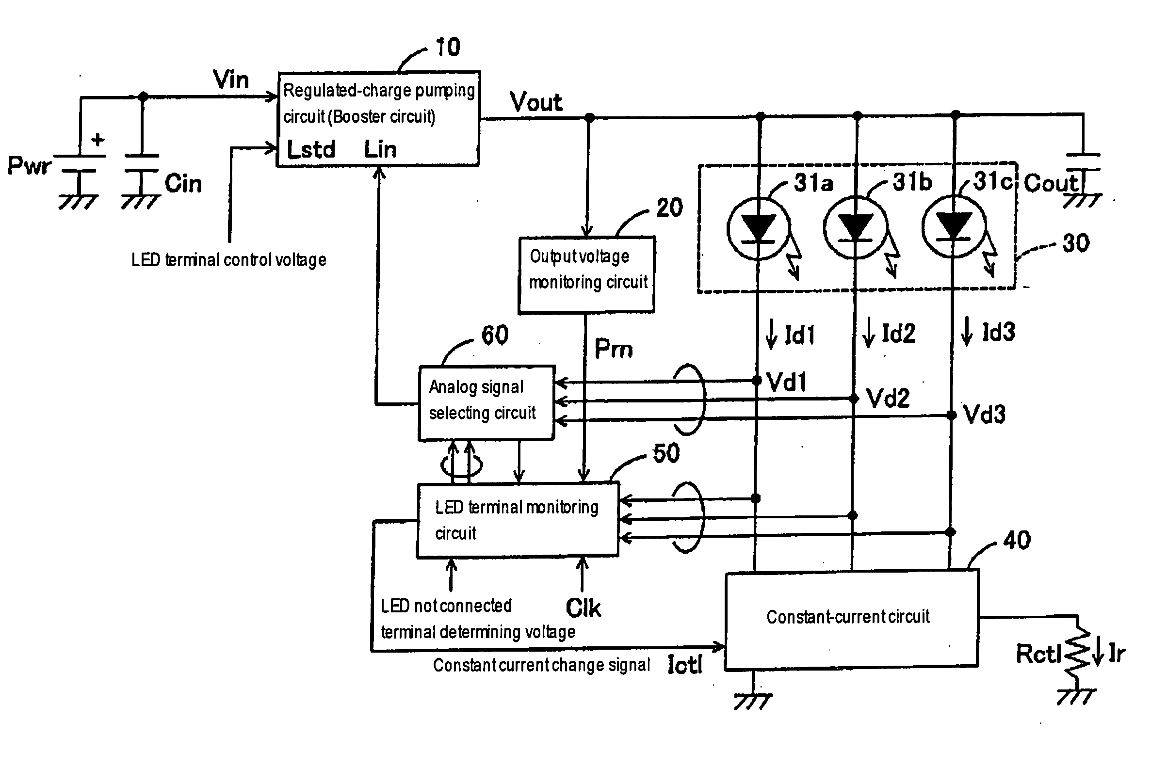
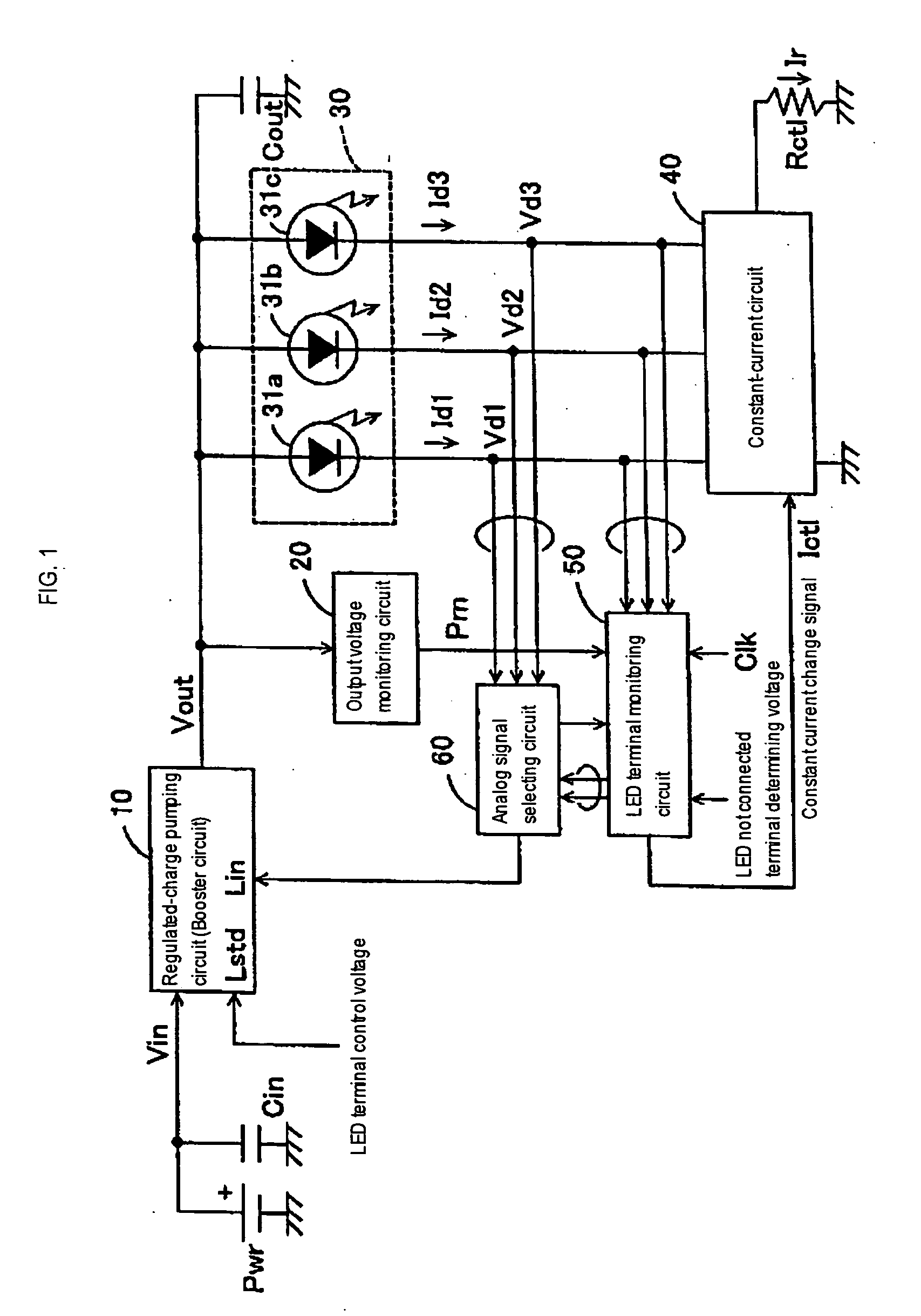
[0021] Referring to FIG. 1 showing an LED-switching controller in a first embodiment according to the present invention, a regulated charge pumping circuit (hereinafter referred to as “boosting circuit”) 10 has an input terminal connected to a dc power supply Pwr and an input capacitor Cin, and an output terminal connected to an output capacitor Cout. The boosting circuit 10 has an LED terminal control voltage input terminal Lstd and an LED terminal voltage input terminal Lin. The boosting circuit 10 performs a boosting operation on the basis of an input voltage applied to the LED terminal voltage input terminal Lin and an LED terminal control voltage applied to the LED terminal control input terminal Lstd.

[0022] An output voltage monitoring circuit 20 monitors the output voltage Vout of the boosting circuit 10. Upon the increase of the output voltage Vout to a predetermined maximum voltage, the output voltage monitoring circuit 20 provides an output monitoring signal Prn. An LED c...

second embodiment

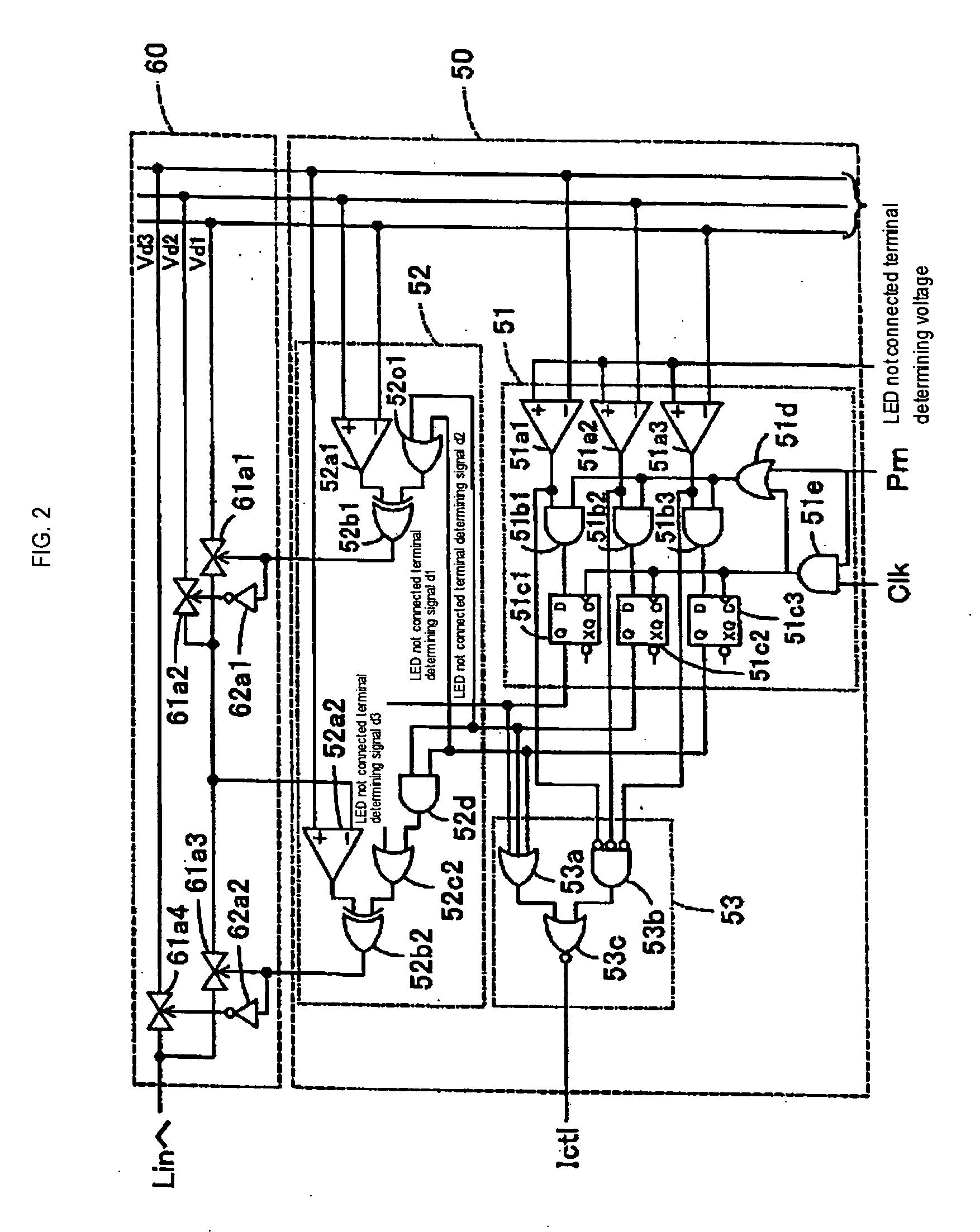
[0046] Although the LED terminal monitoring circuit 50 of the LED-switching controller in the first embodiment is a hardware logic, the LED terminal monitoring circuit 50 can be realized by a software logic.

[0047]FIG. 4 is a block diagram of an LED-switching controller in a second embodiment according to the present invention. The LED-switching controller in the second embodiment is provided with a one-chip microprocessor (hereinafter, referred to simply as “microprocessor”) 70 having functions corresponding to those of the LED terminal monitoring circuit 50 and the analog signal selecting circuit 60 of the LED-switching controller in the first embodiment.

[0048] The microprocessor 70, similarly to the LED terminal monitoring circuit 50, has three input terminals, namely, A / D conversion ports. Signal lines connected to the cathodes of LEDs 31a, 31b and 31c are connected to the input terminals of the microprocessor 70. The microprocessor 70 obtains digital data corresponding to the ...


PUM


Abstract

An LED terminal monitoring circuit detects an LED at the lowest potential among a plurality of parallel-connected LEDs. An analog signal selecting circuit gives a signal indicating the voltage of the detected LED to a boosting circuit. The boosting circuit performs a boosting operation on the basis of the condition of the detected LED at the lowest voltage and, consequently, a voltage sufficient for driving the LEDs in a current-control mode can be applied to all the LEDs. Signal lines not connected to LEDs are excluded from objects of a LED-switching control operation.

Description

BACKGROUND OF THE INVENTION [0001] 1 Field of the Invention [0002] The present invention relates to an LED-switching controller employing a booster for controlling switching parallel-connected LEDs [0003] 2. Description of the Related Art [0004] Recent various electronic devices including cellular phones are provided with a plurality of LEDs for indication and decoration. Cellular phones are subject to restrictions on the capacity of the power supply and most cellular phones are provided with a boosting circuit for switching on the LEDs. A prior art boosting circuit for switching a plurality of parallel-connected LEDs disclosed in U.S. Pat. No. 6,538,394 measures the voltage applied to a signal line connected to any one of the LEDs, and raises the measured voltage to a reference voltage for driving the LED in a current control mode. The reference voltage is determined taking into consideration the different forward voltages necessary for driving the plurality of individual LEDs in a...

Claims


Application Information

Patent Timeline
Patent Type & Authority Applications(United States)
IPC IPC(8): G05F1/00H05B37/02H05B44/00
CPCH05B33/0815Y02B20/347H05B33/0827H05B45/46Y02B20/30H05B45/38
Inventor ITO, SATORUNISHIMURA, SEIJUNFUJIYAMA, TOSHIYA
Owner ASAHI KASEI ELECTRONICS CO LTD
Why Eureka
Try Eureka