Image processing method and device using photo assistant tool including rotator
a technology of assistant tool and image processing device, which is applied in the direction of cameras, television systems, instruments, etc., can solve the problem of small distance between photographic points
- Summary
- Abstract
- Description
- Claims
- Application Information
AI Technical Summary
Benefits of technology
Problems solved by technology
Method used
Image
Examples
embodiment 1
[0033] (Embodiment 1)
[0034] A photographic system according to Embodiment 1 of the present invention uses a photo assistant tool including a plurality of imaging sections for parallax image photography. Stereoscopic photography is carried out while a rotator provided with the plurality of imaging sections is being rotated, thereby realizing the photography of omnidirectional parallax images and providing a binocular stereoscopic vision of such images.
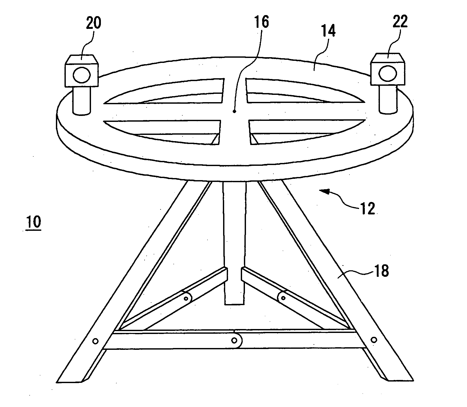
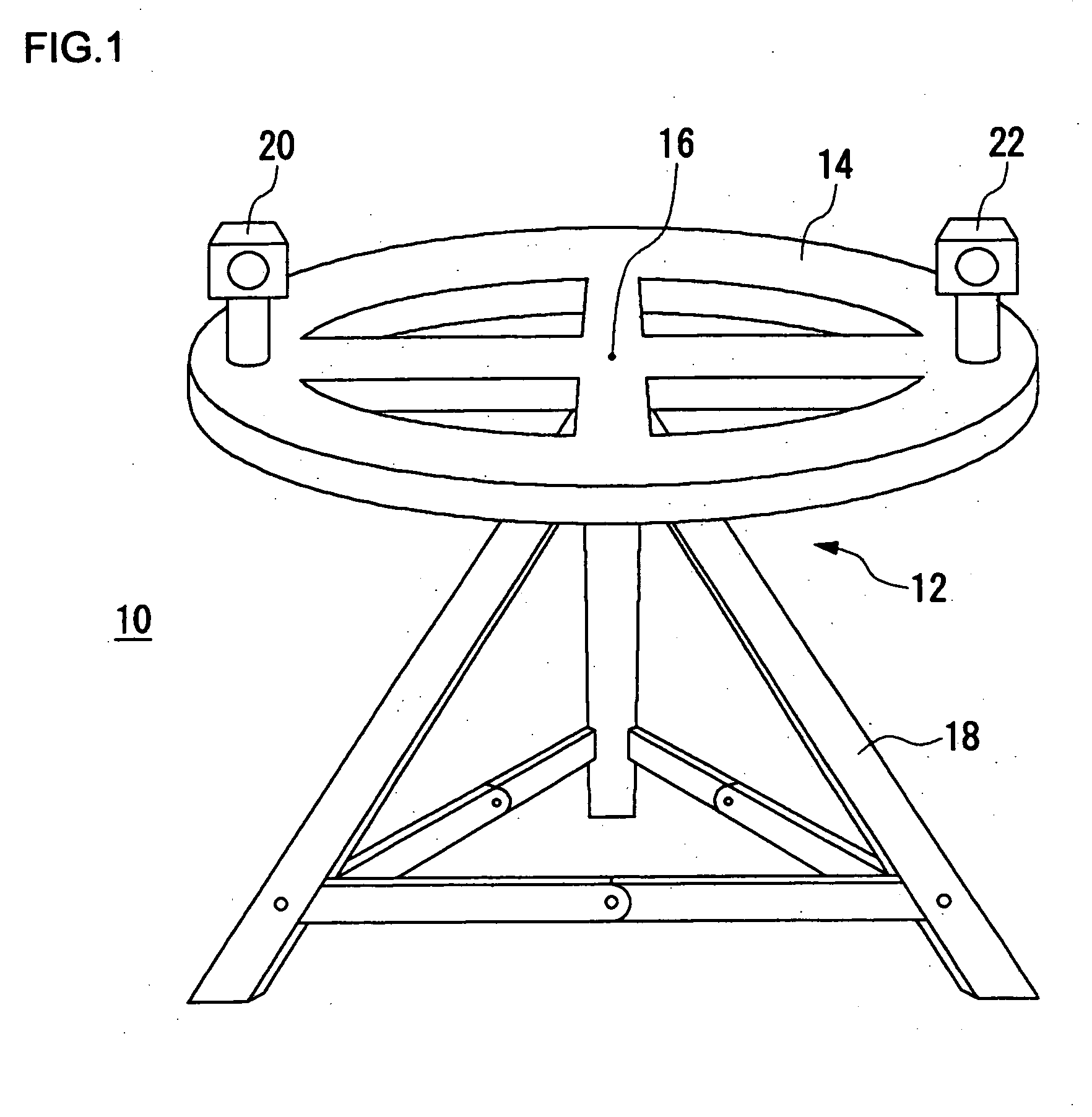
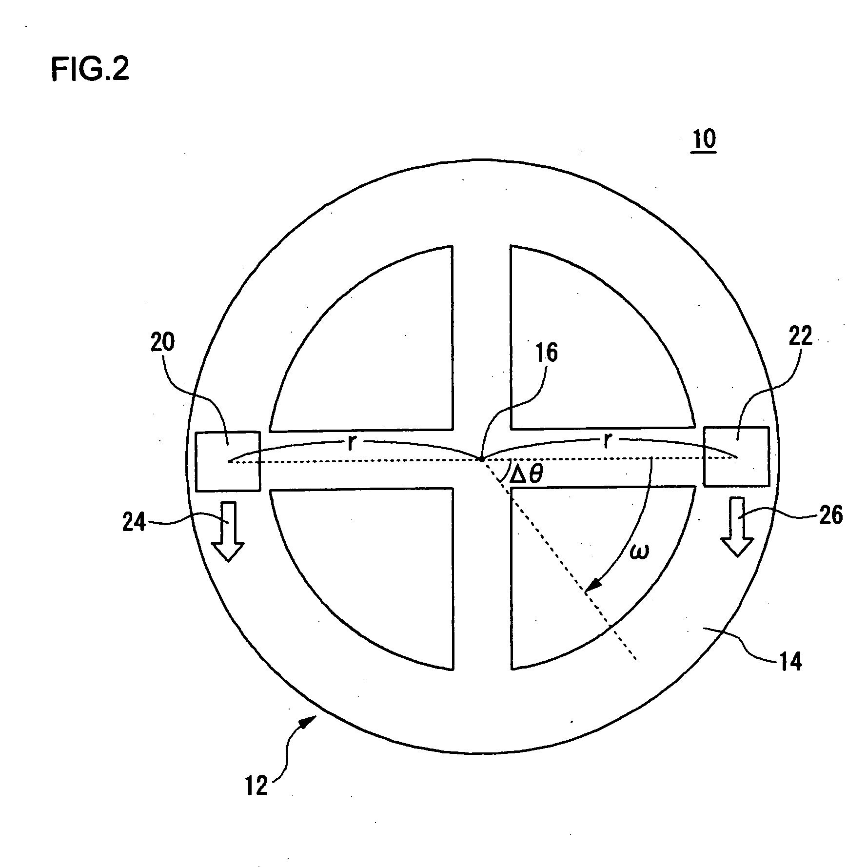
[0035]FIG. 1 shows the outer appearance of a photo assistant tool in a photographic system. A photo assistant tool 12 constituting a photographic system 10 mainly includes: a rotator 14; a plurality of imaging sections 20 and 22; and a support base 18. The rotator 14 is formed by a ring-shaped member and is rotatably supported from its bottom face side with a center 16 of the ring as a center of rotation. The rotator 14 is supported by the support base 18. At the same time, the rotation of the rotator 14 is controlled by a control sect...
embodiment 2
[0054] (Embodiment 2)
[0055] The photo assistant tool 12 in Embodiment 2 of the present invention differs from that in Embodiment 1 in that it has only one imaging section provided for the rotator 14. A method of acquiring parallax images and a method of acquiring an omnidirectional image differ from those of Embodiment 1.
[0056]FIG. 10 shows the outer appearance of the rotator 14 according to Embodiment 2 when viewed from above. In this embodiment, one imaging section 40 is provided at the approximate central position on the right side of the upper surface of the rotator 14 in FIG. 10. The imaging section 40 rotates on its axis independently of the rotation of the rotator 14. The continuous shooting is performed while the imaging section 40 is rotating, thereby obtaining an omnidirectional image. The entire rotator 14 also rotates independently of and in addition to the rotation of the imaging section 40. However, the rotation of the rotator 14 in this embodiment is not continuous a...
embodiment 3
[0060] (Embodiment 3)
[0061] Embodiment 3 of the present invention is common to Embodiment 1 in that the rotator 14 of the photo assistant tool 12 is provided with two imaging sections. However, Embodiment 3 differs from Embodiment 1 in that photographic directions of the two imaging sections are different from each other.
[0062]FIG. 13 shows the outer appearance of the rotator 14 according to Embodiment 3 when viewed from above. On the upper face of the rotator 14, the first imaging section 20 and the second imaging section 22 are provided as a plurality of imaging sections as in Embodiment 1 of the present invention. However, in contrast to Embodiment 1, the first imaging section 20 and the second imaging section 22 are both provided on the right side in FIG. 13 so that their photographic directions 24 and 26 are opposite to each other. The photo assistant tool 12 in this embodiment mainly has three operation modes.
[0063] In the first mode, after taking images in two directions in...
PUM
 Abstract
Description
Claims
Application Information
 - R&D
- Intellectual Property
- Life Sciences
- Materials
- Tech Scout
- Unparalleled Data Quality
- Higher Quality Content
- 60% Fewer Hallucinations
Browse by: Latest US Patents, China's latest patents, Technical Efficacy Thesaurus, Application Domain, Technology Topic, Popular Technical Reports.
© 2025 PatSnap. All rights reserved.Legal|Privacy policy|Modern Slavery Act Transparency Statement|Sitemap|About US| Contact US: help@patsnap.com


