Developing apparatus, process cartridge, electrophotographic image forming apparatus and end portion regulating member
a technology of electrophotographic image and regulating member, which is applied in the direction of electrographic process apparatus, optics, instruments, etc., can solve the problems of developer leakage, developer adhesion to electrophotographic photosensitive member, etc., and achieve good image and reduce developer unnecessarily
- Summary
- Abstract
- Description
- Claims
- Application Information
AI Technical Summary
Benefits of technology
Problems solved by technology
Method used
Image
Examples
first embodiment
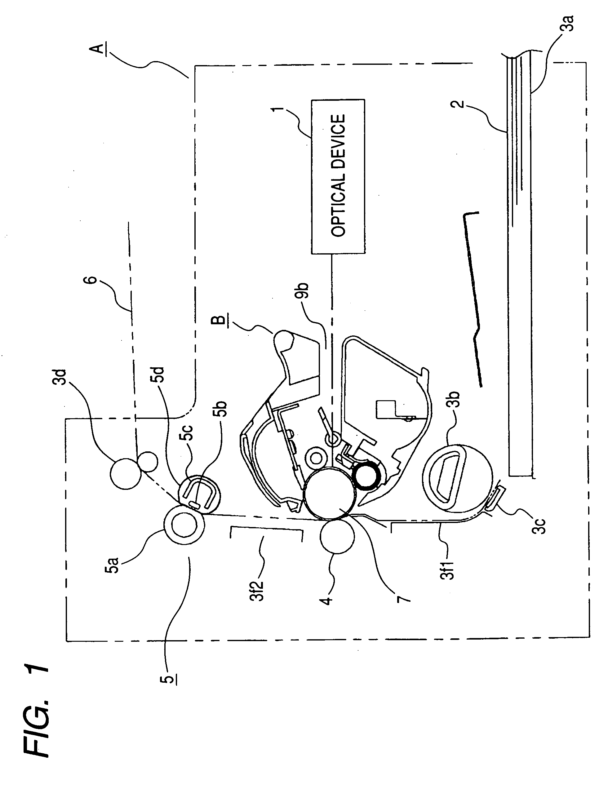
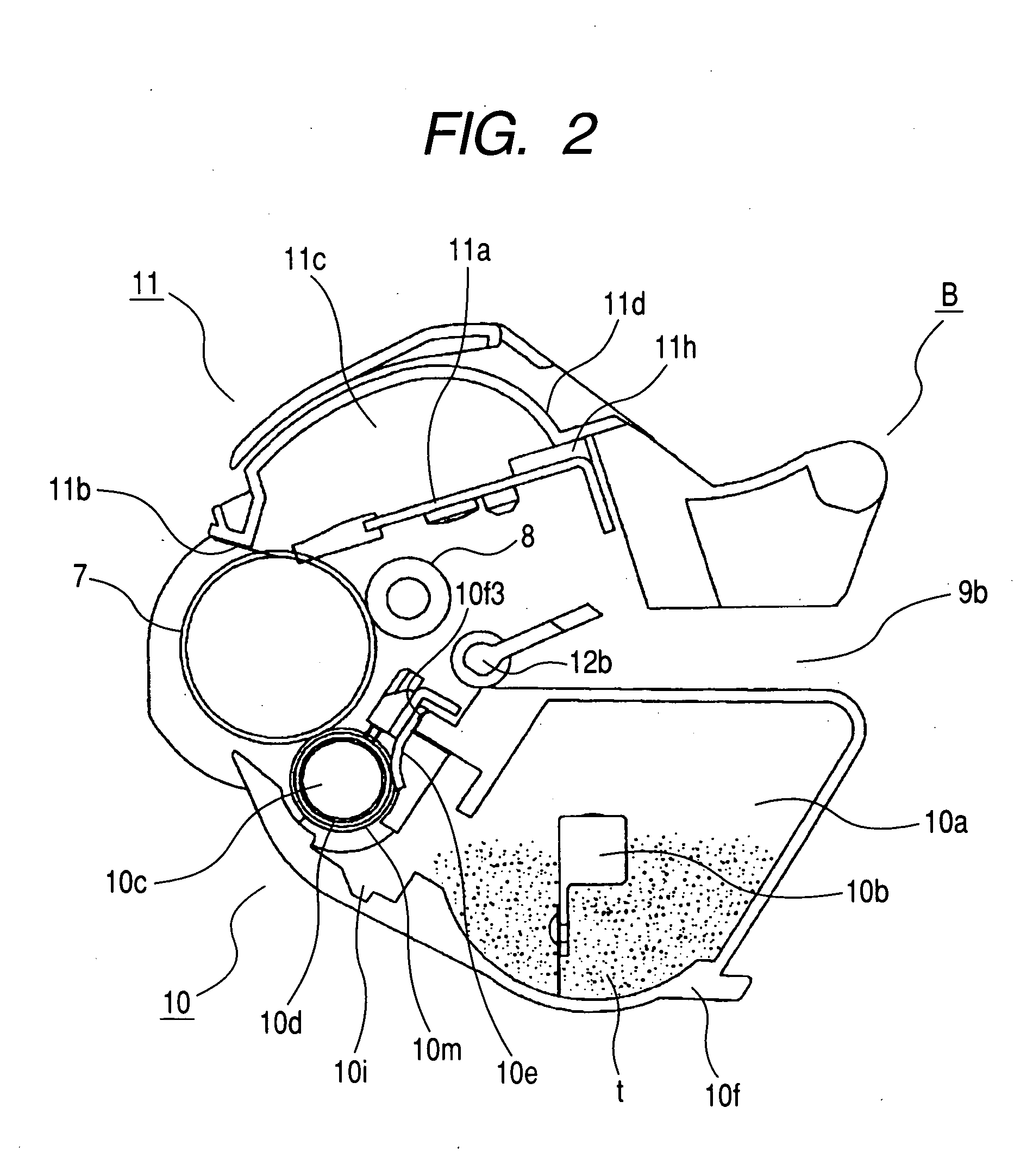
[0034] Reference is first had to FIGS. 1 and 2 to describe a process cartridge and an electrophotographic image forming apparatus to which it is detachably mountable. FIG. 1 is a cross-sectional view showing the construction of an electrophotographic image forming apparatus on which a process cartridge according to the present embodiment is mounted. FIG. 2 is a cross-sectional view showing the construction of a process cartridge according to the present embodiment.
(Electrophotographic Image Forming Apparatus)
[0035] As shown in FIG. 1, the electrophotographic image forming apparatus (laser beam printer, hereinafter referred to as the “image forming apparatus”) A applies light based on image information from an optical device 1 to a drum-shaped electrophotographic photosensitive member (hereinafter referred to as the “photosensitive drum”) 7. Thereby, an electrostatic latent image is formed on the photosensitive drum 7. Then, this electrostatic latent image is developed with a deve...
second embodiment
[0070]FIG. 12 is a fragmentary front view of the developing apparatus as it is seen from Y direction in FIG. 8 with end portion regulating members according to a second embodiment and the developing roller mounted on the developing frame member. FIG. 13A is a side view of the end portion regulating member according to the second embodiment, and FIG. 13B is a front view of the end portion regulating member. FIG. 14 is a cross-sectional view of a developing apparatus according to the second embodiment. FIG. 15 is a fragmentary perspective view of the developing apparatus in a state in which the end portion regulating portions according to the second embodiment and the developing roller are mounted on the developing frame member.
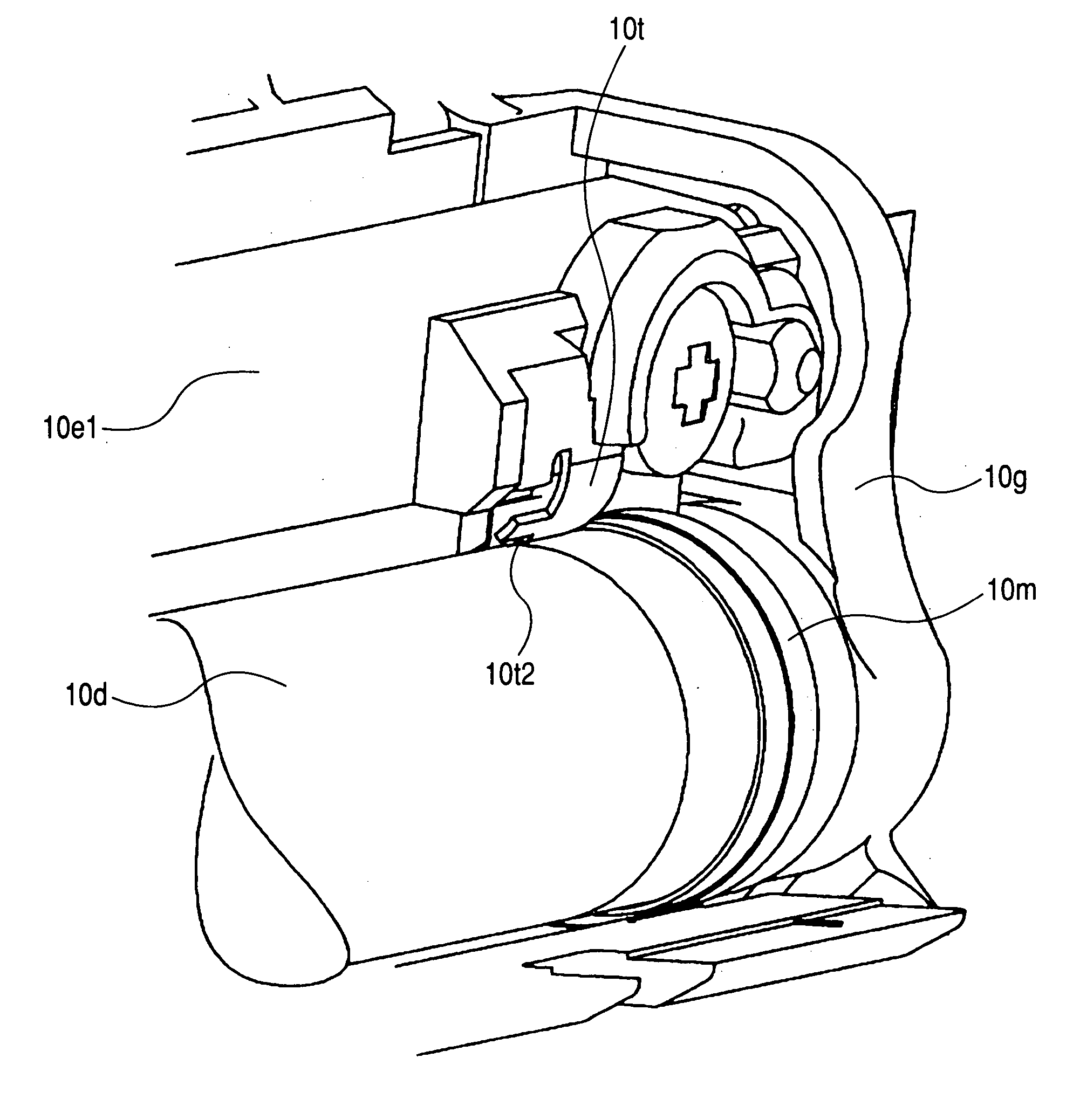
[0071] The regulating portion 10t2 according to the present embodiment is of such a shape that in the longitudinal direction of the developing roller 10d, the distance thereof from the developing roller 10d becomes greater from the outside toward the inside (s...
third embodiment
[0075]FIG. 16 is a fragmentary front view of the developing apparatus in a state in which end portion regulating members according to a third embodiment and the developing roller are mounted on the developing frame member. FIG. 17 is a cross-sectional view of a developing apparatus according to the third embodiment.
[0076] In the present embodiment, as end portion seal members, elastic seal members 10r1 such as felt are brought into contact with the developing roller 10d. That is, by the elastic seal members 10r1, the developer “t” is prevented from leaking out from the end portions of the developing roller 10d to the outside of the cartridge B.
[0077] At this time, there may be formed interstices G1 between the rubber portion 10e2 of the developing blade and the seal members 10r1. Therefore, the regulating portions 10t2 are disposed at a distance G3 from the developing roller 10d at a location whereat they overlap the interstices G1 in the longitudinal direction. As a result, they ...
PUM
 Abstract
Description
Claims
Application Information
 - R&D
- Intellectual Property
- Life Sciences
- Materials
- Tech Scout
- Unparalleled Data Quality
- Higher Quality Content
- 60% Fewer Hallucinations
Browse by: Latest US Patents, China's latest patents, Technical Efficacy Thesaurus, Application Domain, Technology Topic, Popular Technical Reports.
© 2025 PatSnap. All rights reserved.Legal|Privacy policy|Modern Slavery Act Transparency Statement|Sitemap|About US| Contact US: help@patsnap.com


