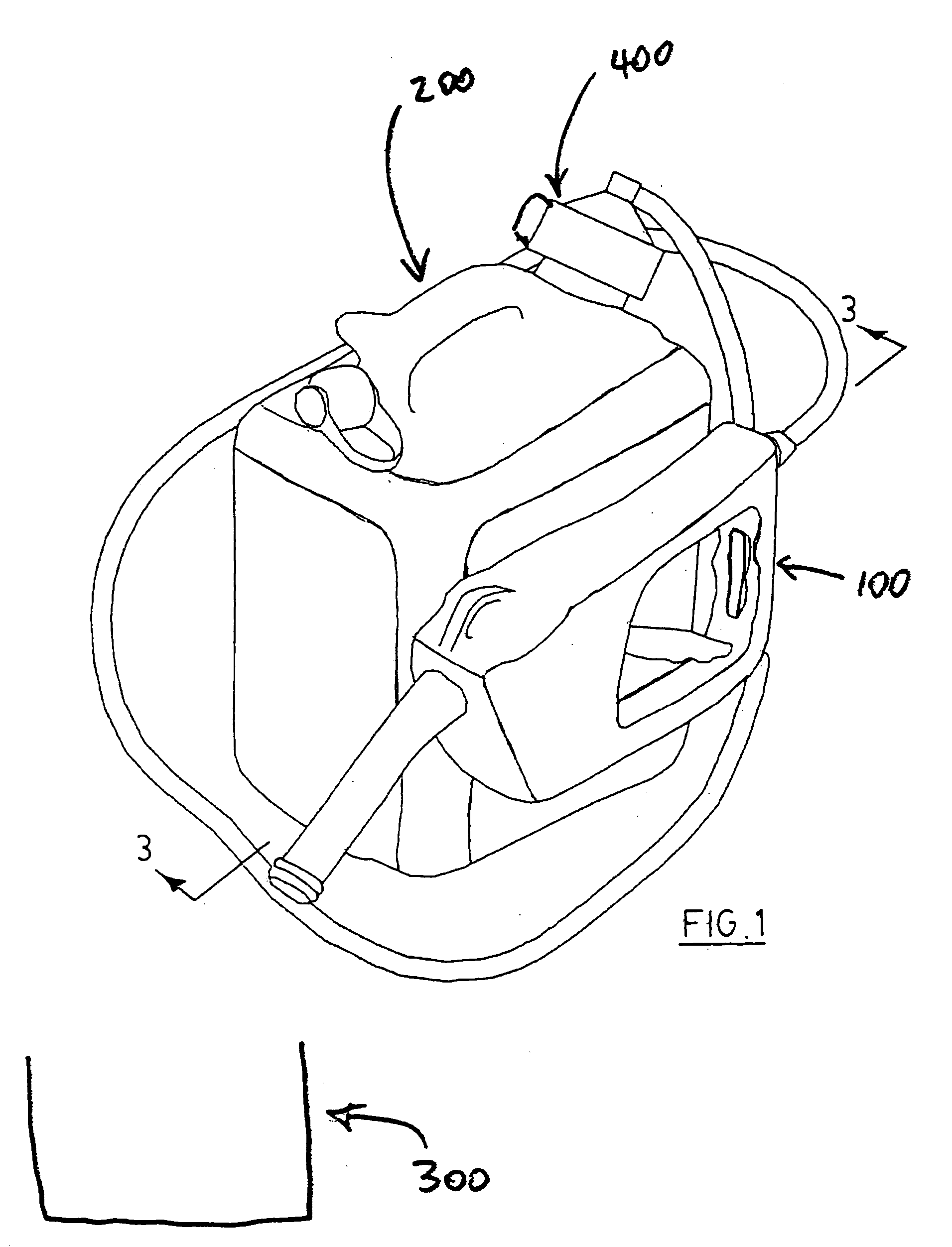
[0003] The present invention provides a combination of a supply container and a fluid transfer apparatus, the fluid transfer apparatus disposed in fluid communication disposition with the liquid in the supply container to thereby effect creation and communication of a reduced
fluid pressure relative to a
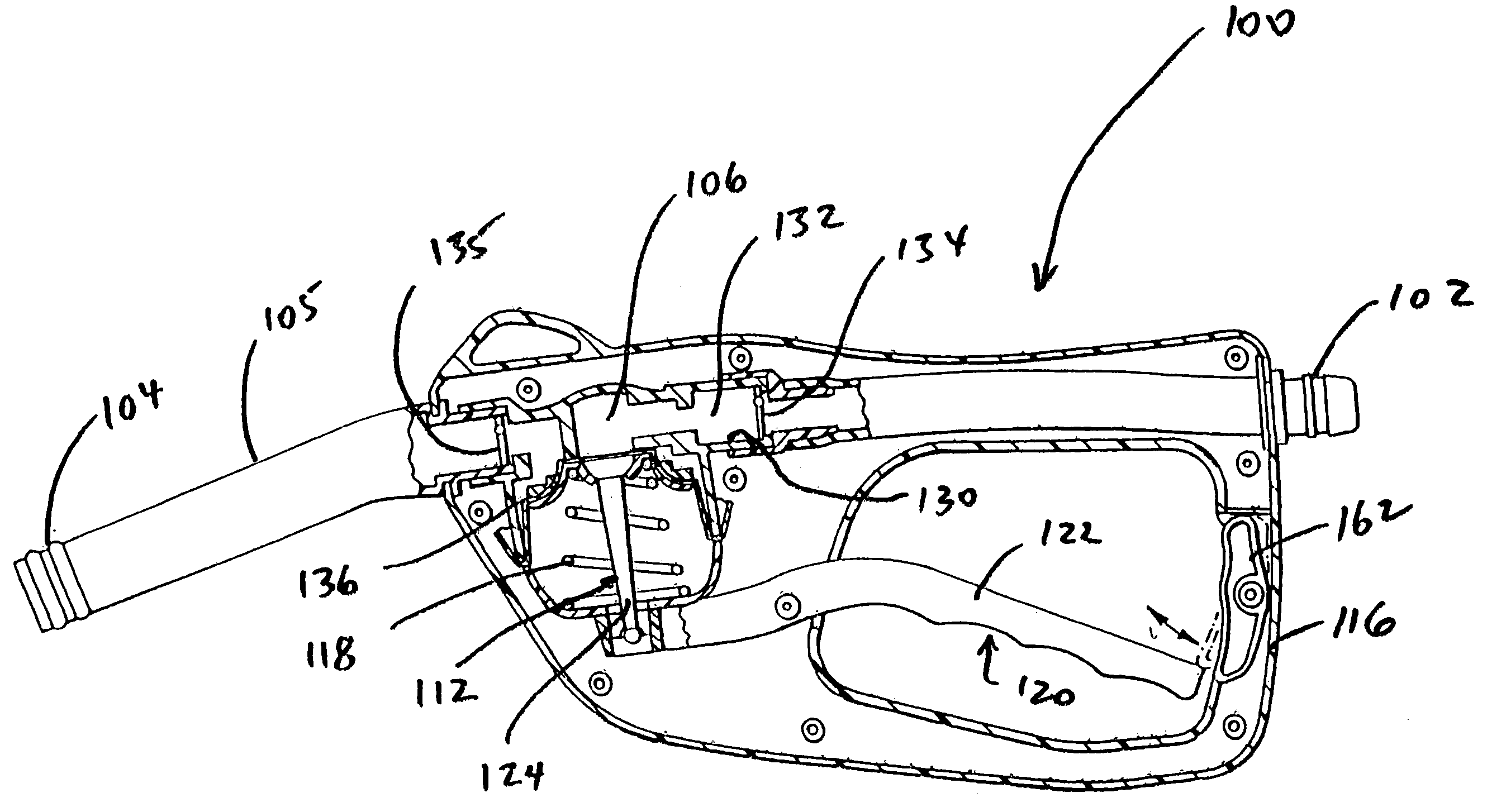
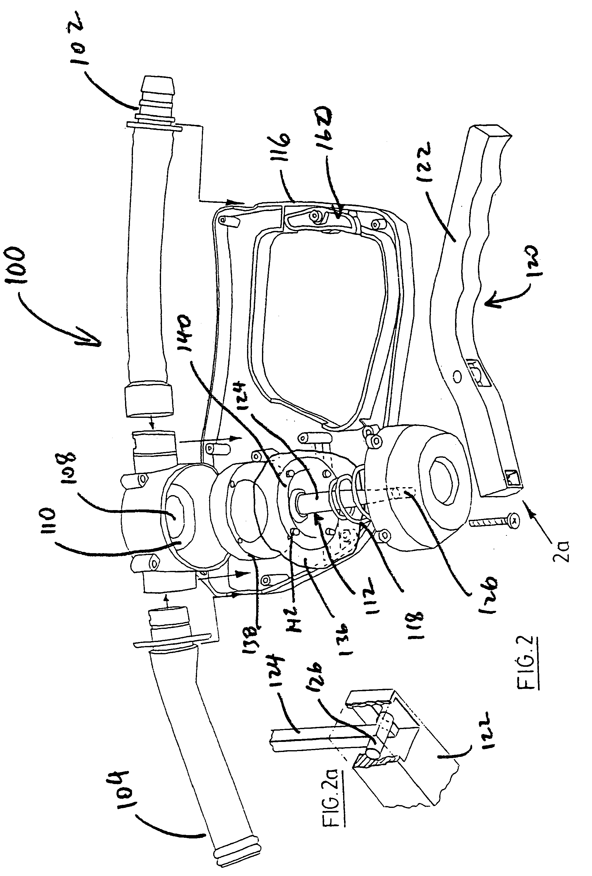
fluid pressure of the liquid in the supply container and thereby initiating flow of the liquid from the supply container, the fluid transfer apparatus comprising a frame, a conduit coupled to the frame and defining a fluid passage, the fluid passage including an inlet, and outlet, and an orifice defined by a valve seat, and the conduit including a conduit section having a flexible containment member and defining a first fluid passage section comprising a space capable of changing its volume, a moveable sealing member, coupled to the flexible containment member, and configured to sealingly engaging the valve seat and an
actuator, pivotally coupled to the frame, and coupled to the sealing member to effect displacement of the sealing member relative to the valve seat in response to pivotal movement of the
actuator relative to the frame, wherein displacement of the sealing member from the valve seat by the
actuator effects the creation and communication of the reduced fluid pressure to the liquid in the supply container.
[0008] The present invention further provides the combination wherein the displacement of the sealing member from the valve seat effects expansion of the space to thereby effect a reduced fluid pressure in the space sufficient to create the sufficient fluid pressure differential between the inlet and the space to overcome the bias of the first valve means to seal fluid communication between the inlet and the space.
[0011] The present invention also provides a fluid transfer apparatus configured for fluid communication disposition with liquid in a supply container to thereby effect creation and communication of a reduced fluid pressure relative to a fluid pressure of the liquid in the supply container and thereby indicating flow of the liquid from the supply container, the fluid transfer apparatus comprising a frame, a conduit coupled to the frame and defining a fluid passage, the fluid passage including an inlet, and outlet, an orifice defined by a valve seat, and the conduit including a conduit section having a flexible containment member and defining a first fluid passage section comprising a space capable of changing its volume, a moveable sealing member, coupled to the flexible containment member, and configured to sealingly engaging the valve seat, and an actuator, pivotally coupled to the frame, and coupled to the sealing member to effect displacement of the sealing member relative to the valve seat in response to pivotal movement of the actuator relative to the frame, wherein displacement of the sealing member from the valve seat by the actuator effects the creation and communication of the reduced fluid pressure to the liquid in the supply container.
[0016] The present invention further provides the combination wherein the displacement of the sealing member from the valve seat effects expansion of the space to thereby effect a reduced fluid pressure in the space sufficient to create the sufficient fluid pressure differential between the inlet and the space to overcome the bias of the first valve means to seal fluid communication between the inlet and the space.
[0019] The present invention further provides a fluid transfer apparatus configured for fluid communication disposition with liquid in a supply container to thereby effect creation and communication of a reduced fluid pressure relative to a fluid pressure of the liquid in the supply container and thereby initiate flow of the liquid from the supply container, comprising a frame, a conduit coupled to the frame and defining a fluid passage, the fluid passage including an inlet, and outlet, and an orifice defined by a valve seat, the conduit including a conduit section having a flexible containment member and defining a first fluid passage section comprising a space capable of changing its volume, a moveable sealing member, coupled to the flexible containment member, and configured for sealingly engaging the valve seat, an actuator, pivotally coupled to the frame, and configured to effect displacement of the sealing member relative to the valve seat in response to pivotal movement of the actuator relative to the frame, and locking means pivotally coupled to the frame and configured to engage the actuator to prevent the actuator from effecting displacement of the sealing member when the sealing member is sealingly engaged to the valve seat, wherein displacement of the sealing member from the valve seat by the actuator effects the creation and communication of the reduced fluid pressure to the liquid in the supply container.
[0020] The present invention further provides the fluid transfer apparatus wherein the locking means is moveable between a locking condition and a disabled condition such that, in the locking condition, the locking means prevents the actuator from effecting displacement of the sealing member when the sealing member is sealingly engaged to the valve seat, and in the disabled condition, the actuator is moveable to effect displacement of the sealing member.

