Method of manufacturing magnetic head

Active Publication Date: 2005-05-19
SAE MAGNETICS H K LTD 50
View PDF1 Cites 2 Cited by
  • Summary
  • Abstract
  • Description
  • Claims
  • Application Information

AI Technical Summary

Benefits of technology

[0014] Focusing on the conventional problems described above, an object of the present invention is to provide a method of manufacturing a magnetic head in which it is possible to perform bonding of a slider and a suspension by taking an ABS pattern that determines flying characteristics as a reference, with no special fabrication required on the slider or the suspension.
[0020] It is not necessary to remeasure the reference in process steps subsequent to attaching of the slider to the suspension provided that the external shape of the slider is previously measured while computing the reference, and relative positions between the external shape of the slider and the reference are stored as associated information. In addition, it becomes possible to read out the measured slider reference simply by measuring the external shape of the slider, and checking the measured values against the associated information. When the slider is then attached to the suspension based on the read out reference, the attachment can be performed taking the engraved region and the other region as a reference, and a balance between positive pressure and negative pressure that the suspension produces in the slider can be well maintained. It thus becomes possible to stabilize the flying attitude and the electrical characteristics of the slider.
[0022] It should be noted that a step between the engraved region and the other region in the ABS has become smaller in present day magnetic heads in order to make the flying height lower. Accordingly, it is difficult to reliably detect the step because the wavelength of normal visible light is long (that is, the engraved region and the other region cannot be clearly identified). Ultraviolet (UV) light has a shorter wavelength than normal visible light. According to the present invention, the step between the engraved region and the other region, which is difficult to detect by normal visible light, can be reliably detected by irradiating UV light onto the engraved region and the other region, and capturing reflected UV light by a UV light detecting camera. The engraved region and the other region can thus reliably be identified through the irradiation of UV light and capturing of the reflected UV light by the UV light detecting camera. It thus becomes possible to improve the reference precision.
[0023] As explained above, according to the present invention, there is provided a method of manufacturing a magnetic head for attaching a slider, on which an ABS is formed, to a suspension, the method including photographing a surface of the slider on which the ABS is formed, identifying the ABS and an engraved region formed within the ABS from a photographed image, computing a reference that serves as a guide in attaching the suspension, and attaching the slider to the suspension based on the reference. Alternatively, there is provided a method of manufacturing a magnetic head for attaching a slider, on which an ABS is formed, to a suspension, the method including photographing a surface of the slider on which the ABS is formed, photographing an external shape of the slider, identifying the ABS and an engraved region formed within the ABS from a photographed image, computing a reference that serves as a guide in attaching the suspension, storing as associated information a positional relationship between the reference and the external shape of the slider, measuring, when attaching the suspension to the slider, the external shape of the slider and reading out the reference by checking measured values against the associated information, and attaching the slider to the suspension based on the reference. Therefore, it becomes possible for positive pressure and negative pressure that occur in the air bearing surface (ABS) to be well balanced centered about the suspension, and a stabilized flying attitude and good electrical characteristics can be obtained.

Problems solved by technology

However, problems like those described below exist with the conventional magnetic head manufacturing methods described above.
The designed flying attitude and electrical characteristics may thus not be obtainable.
Accompanying miniaturization of sliders and more complex ABS patterns (in order to stabilize flying characteristics), it is expected that accurately attaching the suspension by taking the external shape of the slider as a reference will become increasingly difficult.
Furthermore, there is a fear that a balance between positive pressure and negative pressure in the ABS will go out of balance, making it impossible to stabilize the flying attitude of the slider, when forming through holes and the like used for positioning in the slider itself.

Method used


Image

  • Method of manufacturing magnetic head
  • Method of manufacturing magnetic head
  • Method of manufacturing magnetic head

Examples


Embodiment Construction

[0027] Specific preferred embodiments of a method of manufacturing a magnetic head according to the present invention are explained in detail below while referring to the appended drawings.

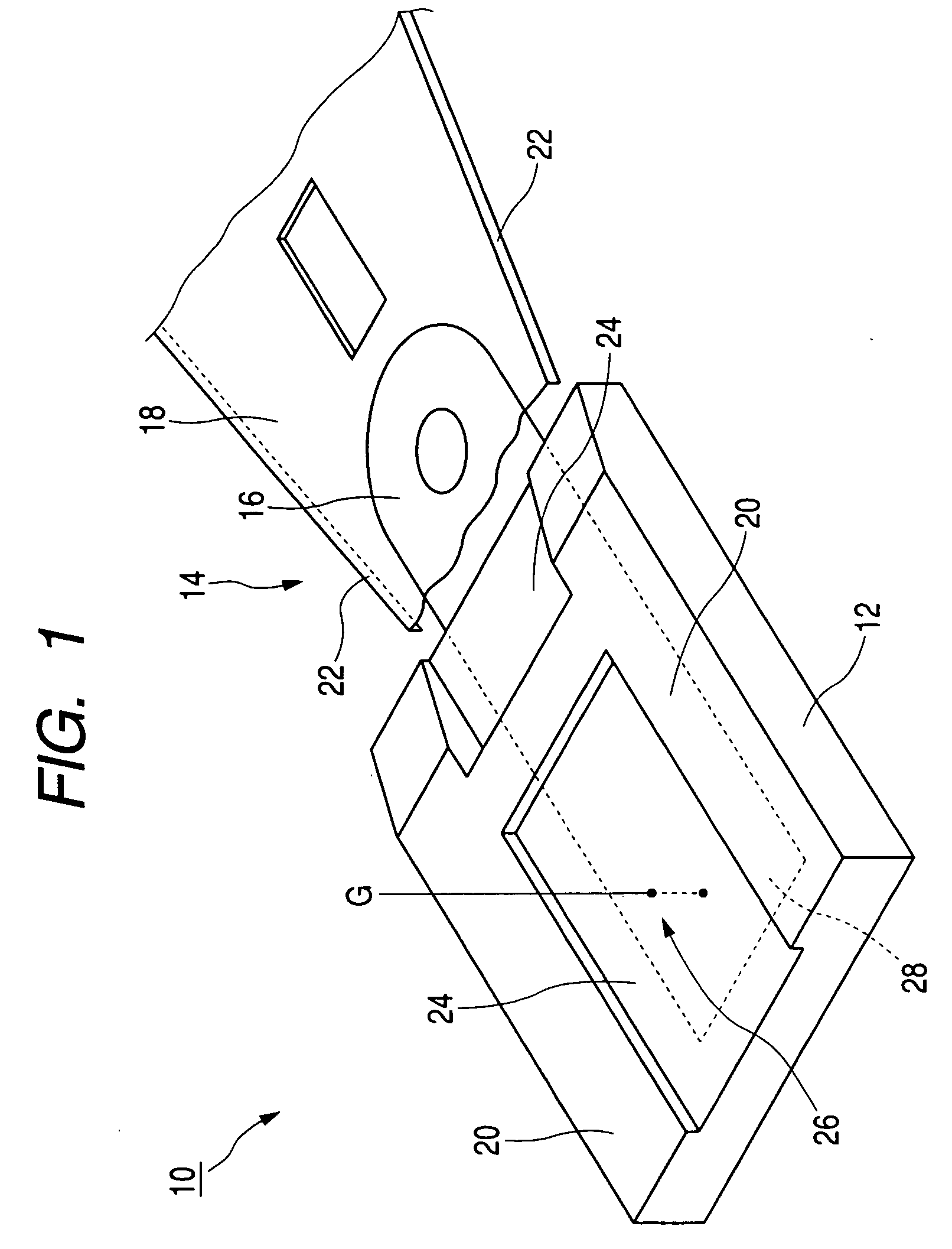
[0028]FIG. 1 is a perspective view of a magnetic head that is manufactured by using a method of manufacturing a magnetic head according to this embodiment. Referring to FIG. 1, a magnetic head 10 that is manufactured by using the method of manufacturing a magnetic head according to this embodiment includes a slider 12 in which giant magneto-resistive (GMR) element is incorporated, and a suspension 14 that is fixed to the slider 12. The suspension 14 includes a flexure 16 that is bonded and fixed to the slider 12, a load beam 18 that is connected to the flexure 16 by spot welding, and a flexible printed circuit (FPC)(not shown) that provides wirings for the GMP element that is formed on the slider 12.

[0029] An ABS is formed on a side of the slider 12 opposed to a magnetic disk (not shown) that is...


PUM


Abstract

Provided is a method of manufacturing a magnetic head with which bonding of a slider and a suspension can be performed by taking an ABS pattern, which determines flying characteristics, as a reference, with no special fabrication required on the slider or the suspension. The method relates to a method of manufacturing a magnetic head for attaching a slider, on which an air bearing surface (ABS) is formed, to a suspension. A surface of the slider on which the ABS is formed is photographed, and the ABS and an engraved region formed within the ABS are identified from the photographed image. Then, a reference that serves as a guide in attaching the suspension is computed, and the slider is attached to the suspension based on the reference. It thus becomes possible for positive pressure and negative pressure that occur in the ABS to be well balanced centered about the suspension, making it possible to stabilize flying attitude and electrical characteristics.

Description

BACKGROUND OF THE INVENTION [0001] 1. Field of the Invention [0002] The present invention relates to a method of manufacturing a magnetic head. In particular, the present invention relates to a method of manufacturing a magnetic head suitable for attaching a slider to a suspension with good accuracy. [0003] 2. Related Background Art [0004] Hard disk drives (hereinafter called HDDs) are increasing in capacity and being made thinner. Together with these advances, magnetic heads (20%, 30% sliders) are also being made smaller. [0005] When bonding a slider, on which a giant magneto-resistive (GMR) element is formed, to a suspension side with conventional processes of manufacturing magnetic heads, positioning of the slider is performed first using the external shape of the slider as a reference. An adhesive agent is applied to a rear surface side of the slider (side opposite to a side where an air bearing surface (ABS) is formed) after positioning the slider, and the slider side is made t...

Claims


Application Information

Patent Timeline
IPC IPC(8): G11B5/60G11B5/48G11B21/21
CPCG11B5/4826G11B5/6005Y10T29/49027Y10T29/49037Y10T29/4903G11B5/3169G11B5/455
Inventor TAKANUKI, KAZUAKISHINDO, OSAMUNAKAO, AKIMASAKANEKO, MASAAKIYAMAGUCHI, SATOSHI
Owner SAE MAGNETICS H K LTD 50
Why Eureka
Try Eureka