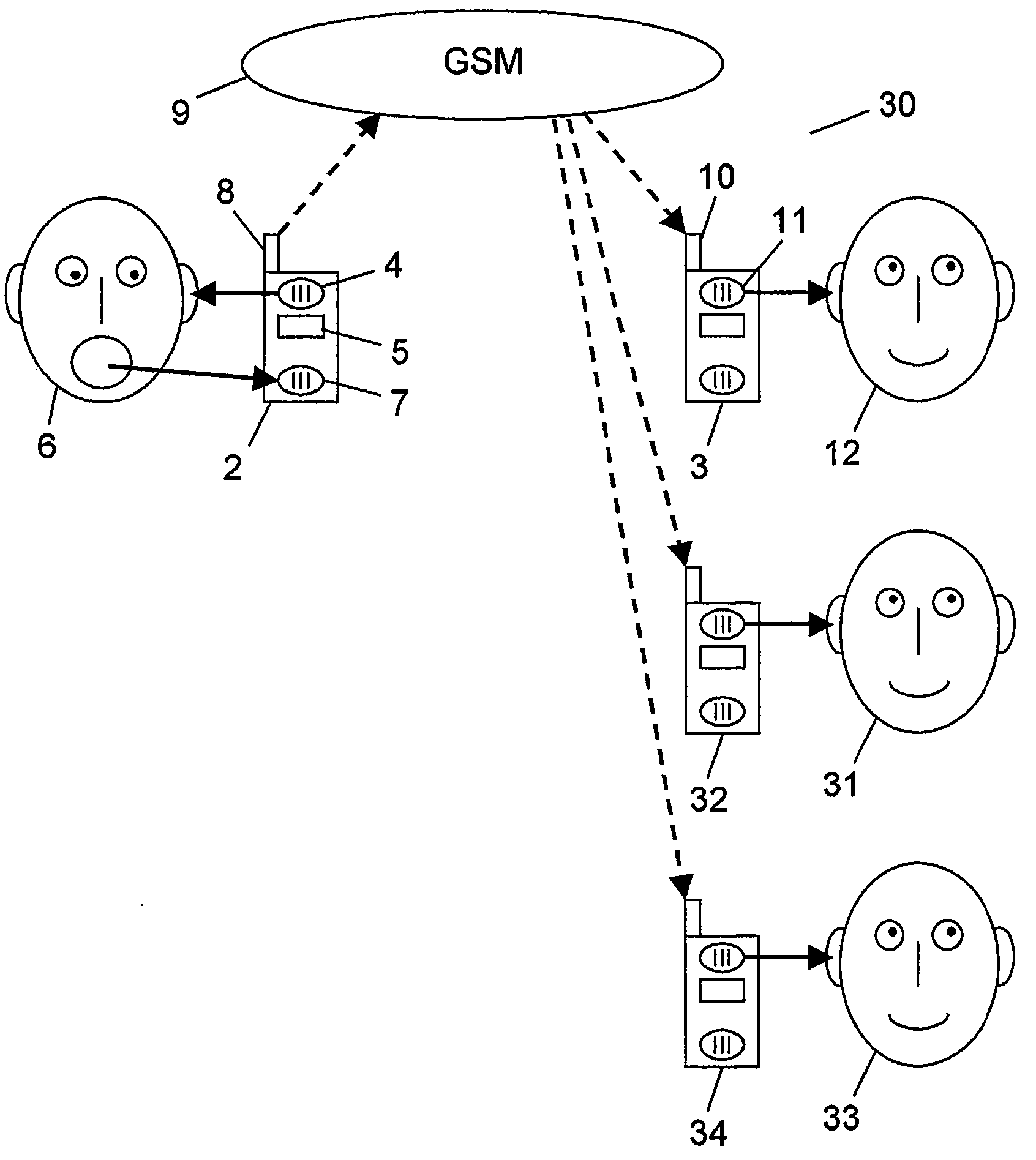
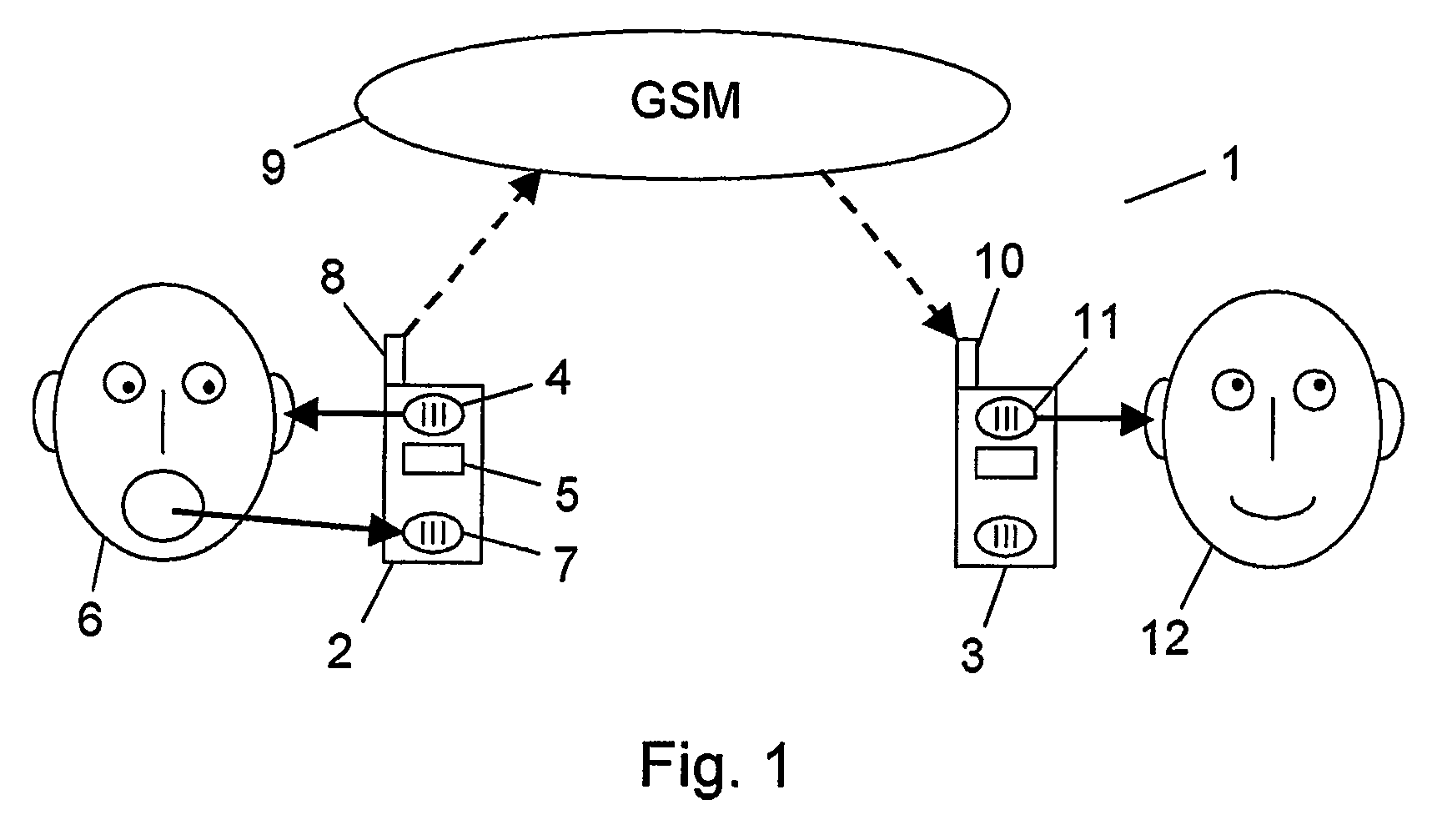
[0041]FIG. 1 shows an example of the use of the invention. In the example a karaoke system 1 is implemented by means of two karaoke devices in the form of the mobile telephones 2 and 3. The mobile telephone 2 is equipped according to the invention, while the telephone 3 may be either a standard mobile telephone or a mobile telephone equipped according to the invention. In FIG. 1 the mobile telephones are illustrated as phones connected to a GSM network, but other types, such as UMTS, GPRS or DECT phones, can be used as well. Also normal stationary telephones may be used. As will be mentioned later, also other types of electronic communications devices may be used.
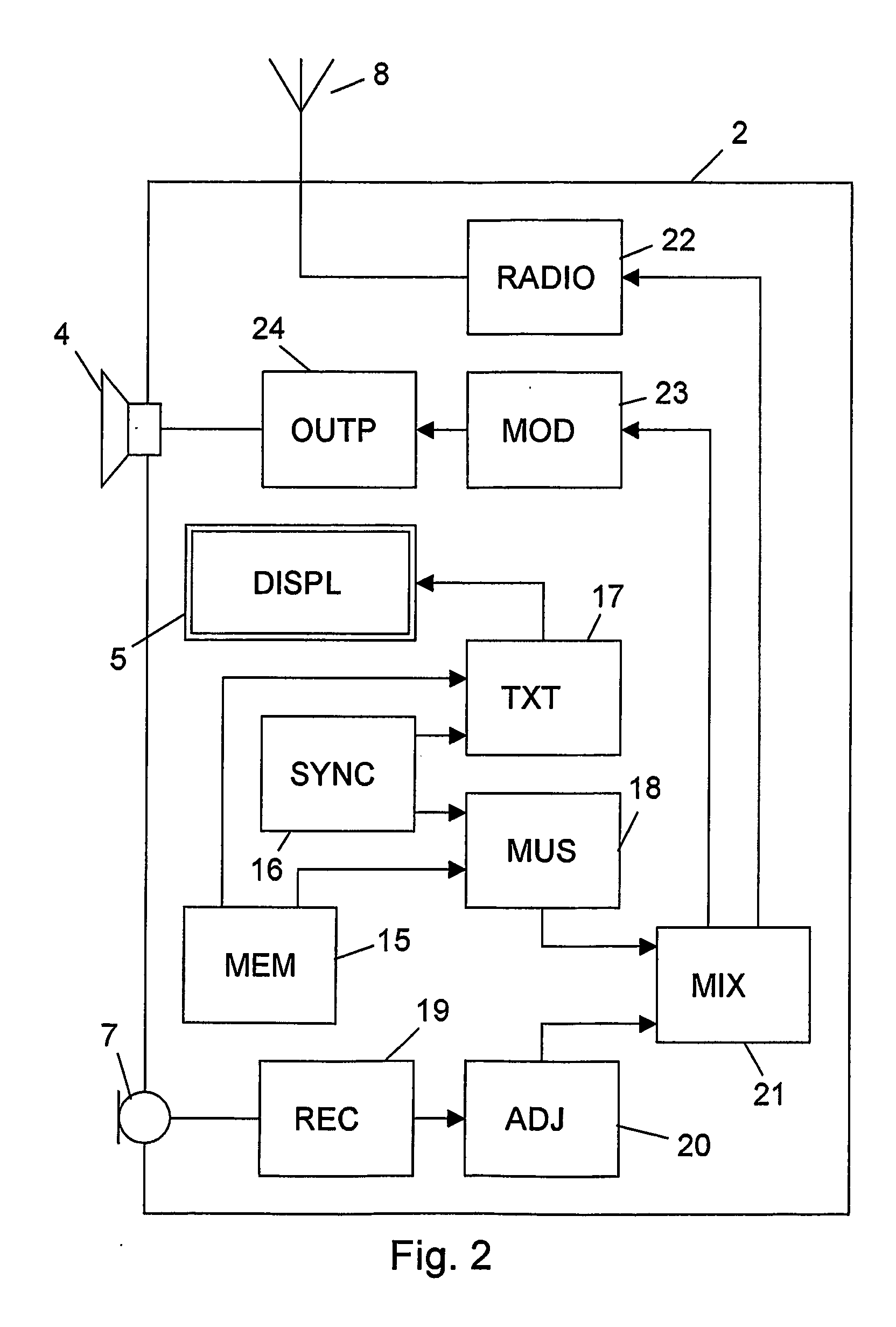
[0042] As will be described in more detail below, the mobile telephone 2 can reproduce the music of a song through the loudspeaker 4 and show the corresponding text of the song on the display 5. A singer 6 listens to the music from the loudspeaker 4 and reads the text on the display 5, which enables him to sing the song into the microphone 7. In the device 2 the voice of the singer is combined with the music and transmitted through the antenna 8 and the GSM network 9 to the other mobile telephone 3, where the combined signal is received by the antenna 10 and reproduced through the loudspeaker 11 to a listening person 12 representing an audience to the karaoke performance.
[0043] It is noted that the sound reproduced by the loudspeaker 4 may be the music signal alone or the music signal combined with the voice of the singer. In the latter case, the voice signal may be modified electronically to provide an improved experience of the singer. Thus this combined signal is not necessarily identical to the one transmitted to the other phone 3.
[0044]FIG. 2 shows an example of how the karaoke device/mobile telephone 2 may be implemented. As mentioned, the device contains circuitry for the karaoke function as well as the circuitry of a normal mobile telephone. For reasons of clarity only those parts of the normal telephone circuitry needed together with the karaoke function are illustrated. FIG. 3 is a flow chart illustrating the function of the system of FIG. 1, and the function will now be described with reference to FIGS. 2 and 3.
[0045] In steps 1 and 2 the data representing the text and the music of a song are read. In the case illustrated in FIGS. 2 and 3 the data of the song are stored in a memory 15 in the phone 2, but as will be mentioned later, this is only one of several possibilities. In addition to the text and the music, optional mood setting pictures to be displayed together with the text of the song may also be stored. The data may be stored in different formats. One possibility could be the planned SMIL multimedia files combining MP3 music, text and optional pictures.
[0046] The playing of the music and the display of the text must be synchronized as illustrated in step 3. This synchronisation is provided by the synchronisation circuit 16 in combination with the text unit 17 and the music unit 18. If the SMIL format is used, the synchronisation is done through that format. If the music and the text are stored in different formats, the text may be controlled by time settings included in the recording of the music, or, although less optimal, the music may be controlled by time settings built into the text. If desired, a speed adjustment may be included, making it possible to adjust the speed of the music and the text.
[0047] In step 4 the text from the text unit 17 is then displayed on the display 5, which is the normal display also used for other purposes in the mobile telephone 2. In case mood creating pictures are also used, these will be displayed on the display together with the text.
[0048] The singer will now read the displayed text and listen to the corresponding music, which is reproduced through the loudspeaker 4, and in parallel to the music he will sing into the microphone 7, which is here the normal microphone of the mobile telephone. The voice of the singer from the microphone 7 is received by the receiving circuit 19 as illustrated in step 5.
[0049] In step 6 the song is adjusted in the adjustment circuit 20 in different ways. The volume compared to the music is set, and in order to compensate for the small microphone and to make the song sound better e.g. more bass and echo may be added.
[0050] As illustrated in step 7 the adjusted voice signal from the singer is then added to or mixed with the music signal from the music unit 18 to create a combined signal. This mixing process is performed in the mixer 21. As shown, the mixer 21 may provide two output signals, one to the singer and one to the audience. As mentioned earlier, these signals may be either identical or different.
[0051] Step 8 now illustrates an important aspect of the invention. The combined signal intended for the audience is transmitted from the mixer 21 through the radio circuit 22, which is the normal radio circuit of the mobile telephone, the antenna 8 and the GSM network shown in FIG. 1 to the other device 3, which is another mobile telephone in this case.
[0052] In the other telephone 3 the received signal may be modified in different ways as illustrated in step 9. As an example, artificial and additionally amplified harmonics and artificial and additionally amplified bass may be generated and added to the signal to compensate for the filtering away of sounds above and below the normal phone frequency range. Similar or other modifications to the signal may also be performed in order to enhance the sound reproduced to the audience. In the latter case such modifications could also have been added to the signal in the mobile telephone 2 before the signal was transmitted to the mobile phone 3, i.e. between the mixer 21 and the radio circuit 22.
[0053] After the modification in step 9 the resulting signal is then played in the loudspeaker 11 to be heard by the audience, which is here represented by the listening person 12. This is illustrated in step 10.
[0054] The output signal from the mixer 21 intended for the singer may also be modified in order to enhance the sound reproduced. This is shown in step 11 and takes place in the modifying circuit 23. If no further modification is needed, this step can be avoided.
[0055] Finally, step 12 shows that this signal is played through the output circuit 24 and the loudspeaker 4 to be heard by the singer. Also the loudspeaker 4 is the normal loudspeaker of the mobile telephone 2.
[0056] The system as described above may be modified in several ways.
[0057] As mentioned earlier, the system may be simplified in such a way that the sound reproduced to the singer by the loudspeaker 4 does not contain the feedback of the singer's own voice. In that case the input of the modifying circuit 23 may be connected directly to the output of the music unit 18 instead of the mixer 21. However, in most situations the feedback to the singer will be preferred, because it provides the singer with an enhanced experience.
[0058] In FIG. 1 only one listener, i.e. the person 12, is illustrated. However, in most karaoke applications the audience will include several listeners. This will be possible if the mobile telephone 3 has a loudspeaking function allowing several people to listen to the loudspeaker 11. The telephone 3 may also be connected, e.g. by a cable, to an external loudspeaker or an audio equipment having its own loudspeakers. Alternatively, the device 3 could be an audio equipment provided with a GSM receiver.
[0059] A more flexible solution is illustrated in FIG. 4 illustrating a system 30, where the signal from the mobile telephone 2 in addition to the mobile telephone 3 is transmitted to the further mobile telephones 32 and 34 allowing the persons 31 and 33 to listen to the karaoke performance on their own mobile telephones. Of course the number of telephones may be further increased corresponding to the size of the actual audience. The persons 12, 31 and 33 may be present in the same room, e.g. the room in which also the singer is present. This situation corresponds to a normal karaoke performance where all participants are in the same room. However, this solution also allows a distributed karaoke performance in which the participants are placed in different locations. As an example, each person may be in his own home. Thus a group of people can enjoy a karaoke performance together at a short notice without having to leave their home.
[0060] In FIG. 4 the karaoke functions must be implemented in the mobile telephone 2, while the telephones 3, 32 and 34 may be normal mobile telephones. However, a more interesting situation is obtained when each member of the group has a mobile telephone in which the karaoke functions are implemented, because it will allow any one of the group participants to be the singer. If e.g. the person 33 wants to be the singer, the karaoke functions will be performed from the telephone 34, while the other telephones will now be in the listening mode.
[0061] In FIG. 1 the mobile telephone 2 is shown to provide the microphone 7 for the singer as well as the loudspeaker 4 and the display 5. In a practical situation this solution is not optimal. One problem is that it will hardly be possible to watch the display 5 when the loudspeaker 4, and thus the complete phone, has to be held close to the ear of the singer in order to listen to the music. While this situation could be overcome by the use of an external display connected to the phone, another problem is the risk of acoustic feedback between the microphone 7 and the loudspeaker 4 resulting in an unwanted acoustical echo.
[0062]FIG. 5 shows a solution to these problems. Here the singer utilizes a second mobile telephone 40, and its loudspeaker 41, to listen to the music. This telephone can then be held to the ear while the singer watches the display 5 and sings into the microphone 7 of the phone 2. The output signal intended for the singer is then transmitted via the GSM network 9 from the phone 2 to the phone 40. This can be implemented by connecting the singer output signal from the mixer 21 in FIG. 2 to the radio circuit 22 instead of the modifying circuit 23. Alternatively, the signal intended for the audience can be used also by the singer. The singer could then just use one of the other phones in FIG. 4 to provide the music.
[0063]FIG. 6 shows another embodiment which also solves the above-mentioned problems. Here a headset 50 is connected to the mobile telephone 2 with a cable 51. The headset 50 is equipped with loudspeakers 52 and 53 and a microphone 54. The singer sings into the microphone 54 and listens to the music through the loudspeakers 52 and 53. He still watches the display 5 of the phone 2. It should be noted that it would also be possible to use the microphone 54 in the headset in combination with the loudspeaker 4 in the phone 2, or the microphone 7 in the phone 2 together with the loudspeakers 52 and 53 in the headset. Instead of the cable 51 the headset 50 could also be connected to the phone 2 by means of a short-range radio link, such as a Bluetooth link.
[0064] Another embodiment of the invention is shown with the system 60 in FIG. 7. Also here a headset is used. However, in this embodiment the circuitry for performing the karaoke function is integrated into the headset 61. Similar to the headset 50 in FIG. 6 the headset 61 has loudspeakers 62 and 63 and a microphone 64. Additionally, the headset 61 comprises circuitry 65 and an antenna 66 for a short-range radio link, such as a Bluetooth link. As mentioned above, headsets with Bluetooth transmitters/receivers already exist, so the only modification needed is the additional karaoke circuitry similar to the one shown in FIG. 2 for the mobile telephone 2. A display for showing the text may be connected to the headset e.g. through a cable or another Bluetooth link. Instead of transmitting the combined signal intended for the audience through a GSM network like in FIG. 1, the signal is here transmitted directly to a Bluetooth receiver. In FIG. 7 the Bluetooth receiver is illustrated as a mobile telephone 67, since many mobile telephones are already equipped with Bluetooth receivers. However, any other device having a Bluetooth receiver could be used. As an example an audio equipment could be provided with a Bluetooth receiver and thus reproduce the karaoke sound for an audience.
[0065] It is noted that Bluetooth and GSM may also be combined. As an example a Bluetooth headset like the one in FIG. 7 could transmit the combined signal to a Bluetooth receiver in e.g. a mobile telephone, from which the signal could be transmitted through a GSM network to a number of other mobile telephones similar to the situation in FIG. 1 or FIG. 4.
[0066] In FIG. 8 an embodiment of the karaoke system 70 using a Personal Digital Assistant (PDA) 71 is illustrated. The karaoke functions from FIG. 2 are here integrated into the PDA 71 having a display 72 larger than the display 5 of the mobile telephone 2. Just like the telephone 2 in FIG. 6 the PDA 71 is connected to a headset 50 with a cable 51. The headset functions as described in FIG. 6. The PDA 71 further has a Bluetooth antenna 73 from which the combined signal can be transmitted to the Bluetooth receiver 67 which can be identical to the one described in FIG. 7.
[0067] In the embodiments described above the data representing the text and the music of a song to be used in a karaoke performance were stored in a memory 15 in the karaoke device, e.g. the mobile telephone 2. This solution has the limitation that typically only a few different songs can be stored due to the limited storage capacity of the memory 15. Instead of the internal memory 15 an external memory in the form of e.g. a memory card may be used, provided that the device is equipped with the necessary hardware for the insertion of such a memory card into the device. An accessory device including the memory and connectable to the karaoke device, e.g. the mobile phone 2, may also be used. These solutions provide a better but still limited selection of different songs.
[0068] A different solution providing a much larger selection of different songs is illustrated in FIG. 9. A remote server 81 having a large selection of different songs is connected to the GSM network 9, e.g. through the Internet. When a user, e.g. the singer 6, wants a specific song for a karaoke performance, this song may be requested from the server 81 by the mobile telephone 2. Subsequently the data corresponding to the requested song are downloaded or streamed to the telephone 2.
[0069] When the data are downloaded, they will typically be stored in the memory 15 in the telephone 2, and then afterwards they can be read therefrom, as was described in relation to FIG. 2. Thus the only modification of FIG. 2 is a connection from the radio circuit 22 to the memory 15 allowing the data to be stored, but such a connection will normally be in the mobile telephone anyway.
[0070] In the case of streaming, the data are transmitted to the mobile phone 2 during the karaoke performance, and the music and the text will then be generated as the data are received. However a buffer is needed in order to avoid any gaps in the music due to transmission errors or delays. Normally, the memory 15 can be used as the buffer, and thus the circuit can be similar to the downloading case.
[0071] Although a preferred embodiment of the present invention has been described and shown, the invention is not restricted to it, but may also be embodied in other ways within the scope of the subject-matter defined in the following claims.