Hair dryer

a hair dryer and dryer technology, applied in the field of hair dryers, can solve the problems of headache, dermatitis and chronic fatigue, easy failure to shield the magnetic field, etc., and achieve the effect of preventing the transmission of the magnetic field

Inactive Publication Date: 2005-05-26
PARK SU HONG
View PDF5 Cites 17 Cited by
  • Summary
  • Abstract
  • Description
  • Claims
  • Application Information

AI Technical Summary

Benefits of technology

[0012] The present invention solves the foregoing problems. It is an object of the present invention to provide a hair dryer that prevents transmitting of the magnetic field to the user of the hair dryer by installing a shielding member in the interior of the dryer housing.

Problems solved by technology

Moreover, it causes problems for human beings such as headache, dermatitis and chronic-fatigue.
Furthermore, a conductive material easily shields the electric field of the electromagnetic wave but easily fails to shield the magnetic field.
Thus, there is the problem that the magnetic field is directly transmitted to the body of the user.

Method used


Image

  • Hair dryer
  • Hair dryer
  • Hair dryer

Examples


example 1

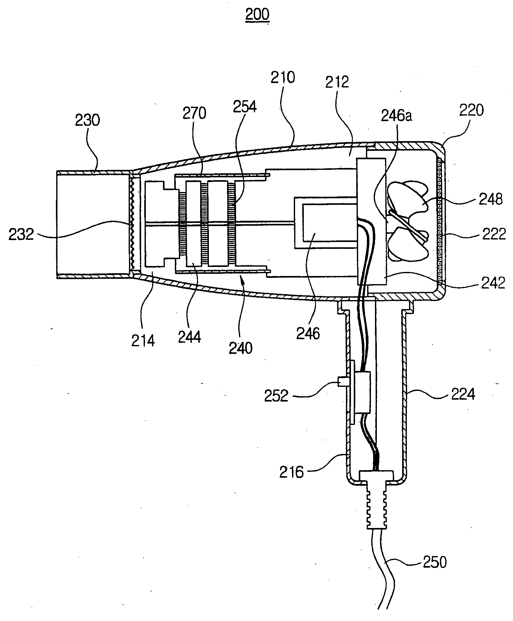
[0034]FIG. 1 is a view showing an installed state of a shielding member 270 at a portion of a heating wire 254 of a hair dryer 200 according to the first embodiment of the present invention.

[0035] Referring to FIG. 1, the hair dryer 200 includes a dryer housing 210, an intake cover 220 and a nozzle 230. Further, a heating assembly 240 is installed at the interior of the dryer housing 210 and the intake cover 220.

[0036] An inlet port 212 and an outlet port 214 are formed at both ends of the interior of the dryer housing 210. In other words, the inlet port 212 is formed at one end of the dryer housing 210, and the outlet port 214 is formed at the other end of the dryer housing 210. A front handle 216 protrudes downwardly from an outer periphery surface of the dryer housing 210. The intake cover 220 is coupled to the rear side of the dryer housing 210.

[0037] An air inlet 222 is integrally formed with an outer surface of the intake cover 220.

[0038] A rear handle 224 corresponding to...

example 2

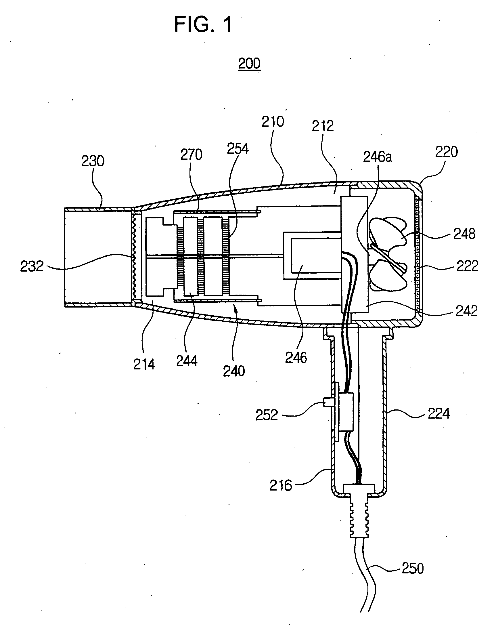
[0048]FIG. 2 is a view showing an installed state of a shielding member 370 at a portion of the driving motor 246 of the hair dryer 200 according to the second embodiment of the present invention.

[0049] As shown in FIG. 2, preferably, the shielding member 370 is cap-shaped, which has an opened portion 371 at a one surface of thereof. The opened portion 371 of the shielding member 370 is mounted on the front surface of the assembly body 242, and the other portion 372 is in contact with the support frame 244. Thus, the shielding member 370 covers the driving motor 246.

[0050] At this state, the user turns on the electrical switch 252 of the hair dryer 200. And then, the driving motor 246 is rotated by the signal of the electrical switch 252. With this process, the magnetic field, which is generated around the driving motor 246, is absorbed and shielded by the shielding member 370.

[0051] In other words, the shielding member 370 prevents magnetic field from transmitting the outside of...

example 3

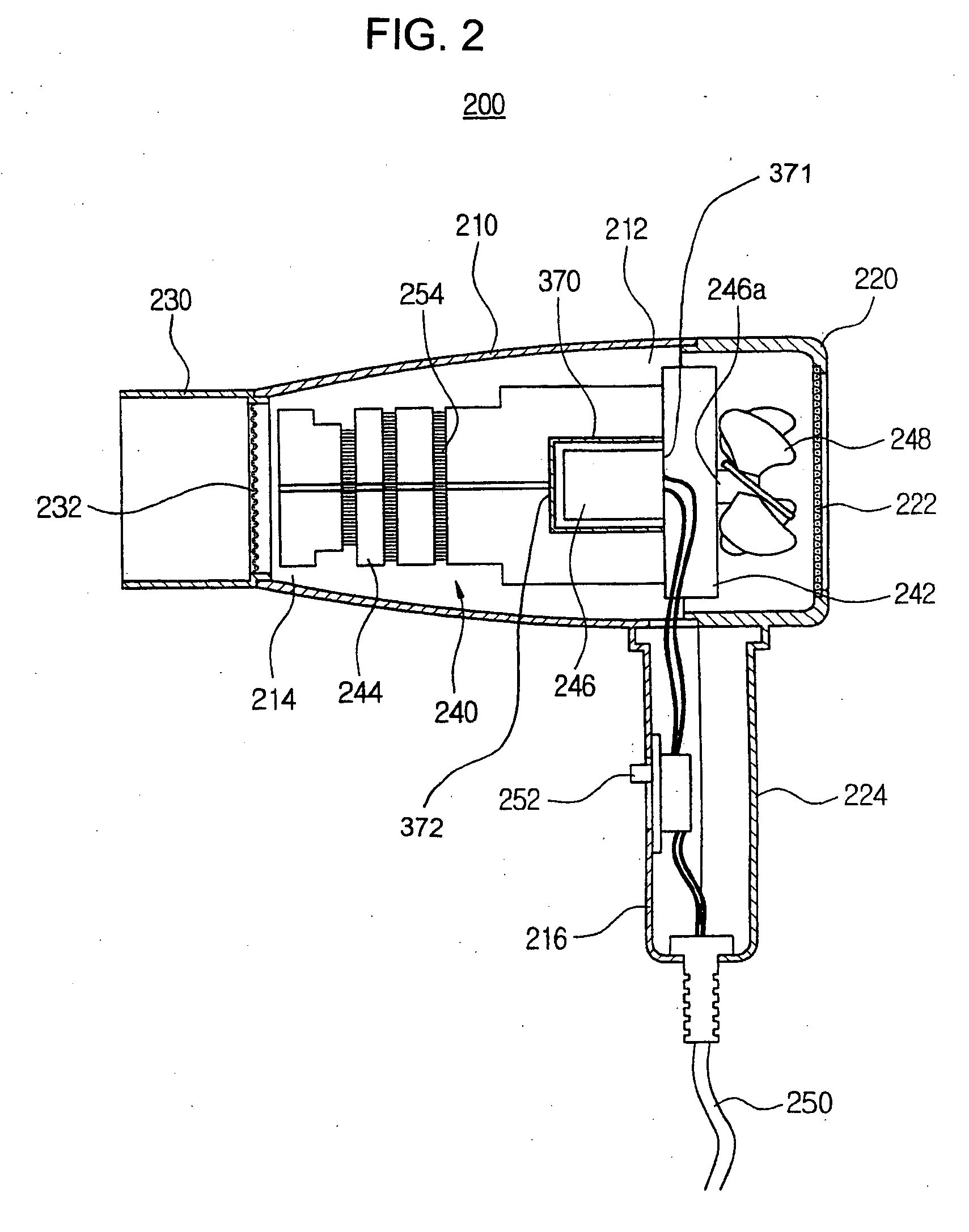
[0052]FIG. 3 is a view showing an installed state of a shielding member 470 at a portion of the blowing fan 248 of the hair dryer 200 according to the third embodiment of the present invention.

[0053] As shown in FIG. 3, preferably, the shielding member 470 is cylindrical shaped. One end of the shielding member 470 receives the rear side of the assembly body 242 so as to cover the blowing fan 248. Preferably, the shielding member 470 is spaced from the intake cover 220 and the air inlet 222. Alternatively, the shielding member 470 may be contacted with the intake cover 220 and the air inlet 222.

[0054] In this state, when the user turns on the electrical switch 252 of the hair dryer 200, the driving motor 246, is driven and the heating wire 254 is heated. The magnetic field is generated around the driving motor 246 and the heating wire 254, and then the magnetic field may be leaked to the intake cover 220. With this construction, the magnetic field, which is generated around the dri...


PUM


Abstract

Disclosed is the hair dryer. In the hair dryer, a hollow dryer housing has an inlet port, an outlet port and a front handle. An intake cover is coupled to a rear side of the dryer housing and has a rear handle protruding downwardly from the hollow dryer, for suctioning an outer air into the dryer housing. A nozzle is coupled to the outlet port of the dryer housing. A heating assembly is positioned in the dryer housing and in the intake cover, and includes a hollow assembly body, a support frame, a driving motor, a rotating shaft, and a blowing fan. A shielding member is installed along an inner side of the dryer housing, the intake cover, and the nozzle. Due to this structure, the hair dryer is capable of absorbing and shielding the magnetic field not to cause human problems such as headache, dermatitis and chronic fatigue.

Description

RELATED APPLICATION [0001] This application is a continuation-in-part of U.S. patent application Ser. No. 10 / 420,088, filed Apr. 22, 2003.CLAIMING FOREIGN PRIORITY [0002] The applicant claims and requests a foreign priority, through the Paris Convention for the Protection of Industry Property, based on a patent application filed in the Republic of Korea (South Korea) with the filing date of Apr. 22, 2002, with the patent application number 20-2002-0012176, by the applicant. BACKGROUND OF THE INVENTION [0003] The present invention relates to a hair dryer, more particularly, it relates to a hair dryer having a shielding function against magnetic field, which is used for drying and styling hair. [0004] A hair dryer, which applies an electrical power of a power supplying part to a dryer body, is used to dry and style the hair by blowing warm or cool air. [0005] Various technical models of the hair dryer have been proposed. The common type of hair dryer will be described herein with refe...

Claims


Application Information

Patent Timeline
Patent Type & Authority Applications(United States)
IPC IPC(8): A45D20/00A45D20/12B62D25/20
CPCA45D20/12A45D20/04
Inventor PARK, SU-HONG
Owner PARK SU HONG
Why Eureka
Try Eureka