Two piece air duct section

a two-piece air duct and conduit technology, applied in the direction of ducting arrangement, lighting and heating apparatus, heating types, etc., can solve the problems of dragging, injuring the fingers and hands of the installer, hazardous and frustrating installation of sheet metal duct work, etc., to minimize air leakage

Inactive Publication Date: 2005-05-26
SNYDER NAT CORP
View PDF9 Cites 26 Cited by
  • Summary
  • Abstract
  • Description
  • Claims
  • Application Information

AI Technical Summary

Benefits of technology

[0008] The invention provides an air duct section that is formed from at least two longitudinal duct portions that snap together to form a hollow duct having a longitudinal direction. The duct section has a pair of ends that are adjustable between male and female configurations. The interlocking device used to connect the duct portions allows continuous adjustability between the first end and the second end of the duct section while minimizing air leaks and providing structural integrity to the duct section.

Problems solved by technology

As most HVAC installers know, installing sheet metal duct work is hazardous and frustrating when the installer must customize a standard-length duct section to fit a specific location on the job.
The customization process typically involves cutting the sheet metal material which produces a sharp, and at times ragged, edge that can injure the fingers and hands of the installer.
In addition to the sharp edges created by customizing a standard-length duct, the process of cutting a round or rectangular duct to length is somewhat difficult and time consuming.
In addition to the installation problems, existing metal duct sections must be fabricated in the field from flat sheet metal or must be shipped in large shipping containers that necessarily contain a large volume of air.
Although the large volume of air is not heavy, the containers are rather large.
The large containers increase the cost of shipping sheet metal ducts from manufacturers to users.

Method used


Image

  • Two piece air duct section
  • Two piece air duct section
  • Two piece air duct section

Examples


Embodiment Construction

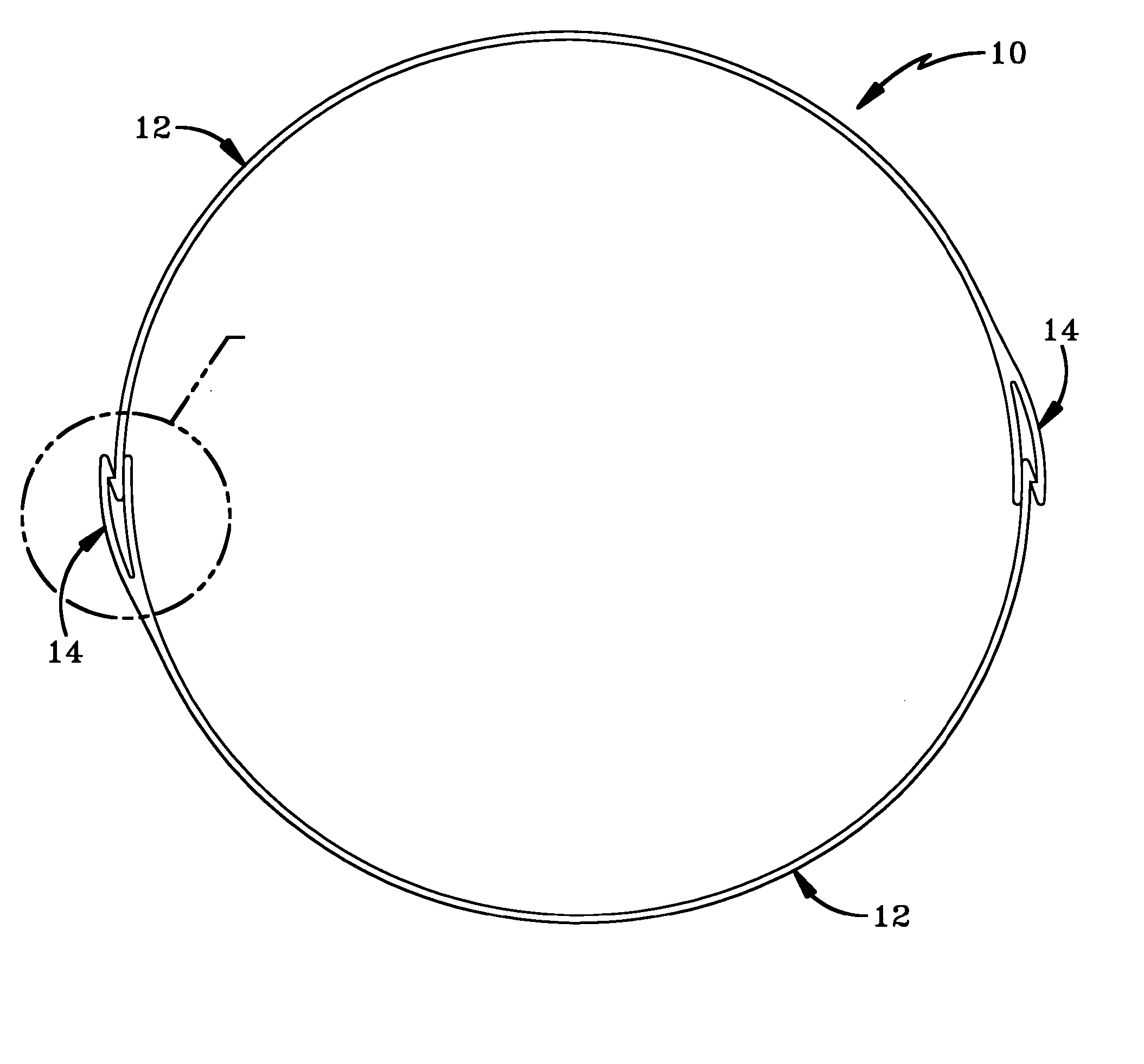
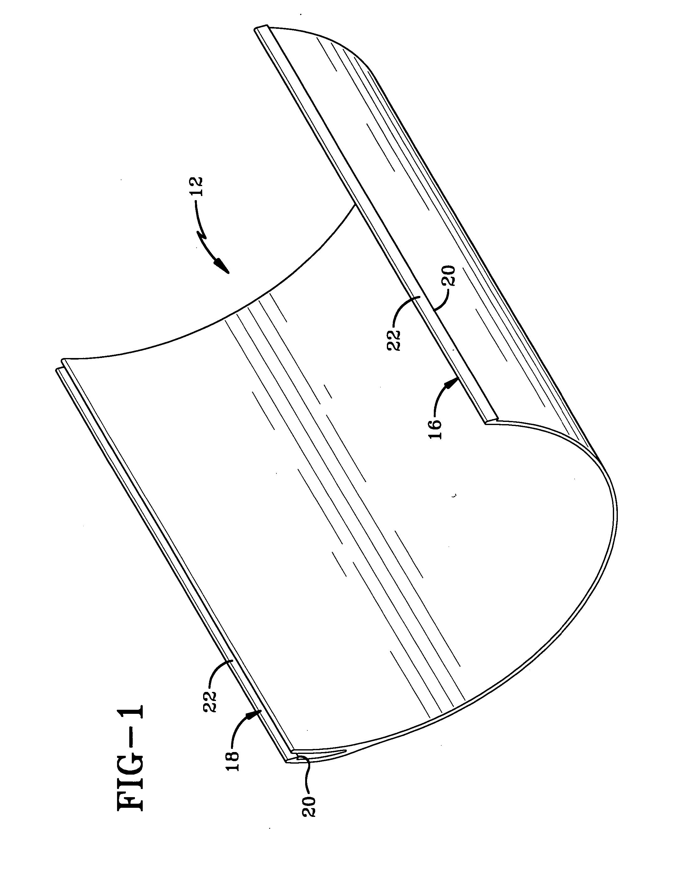
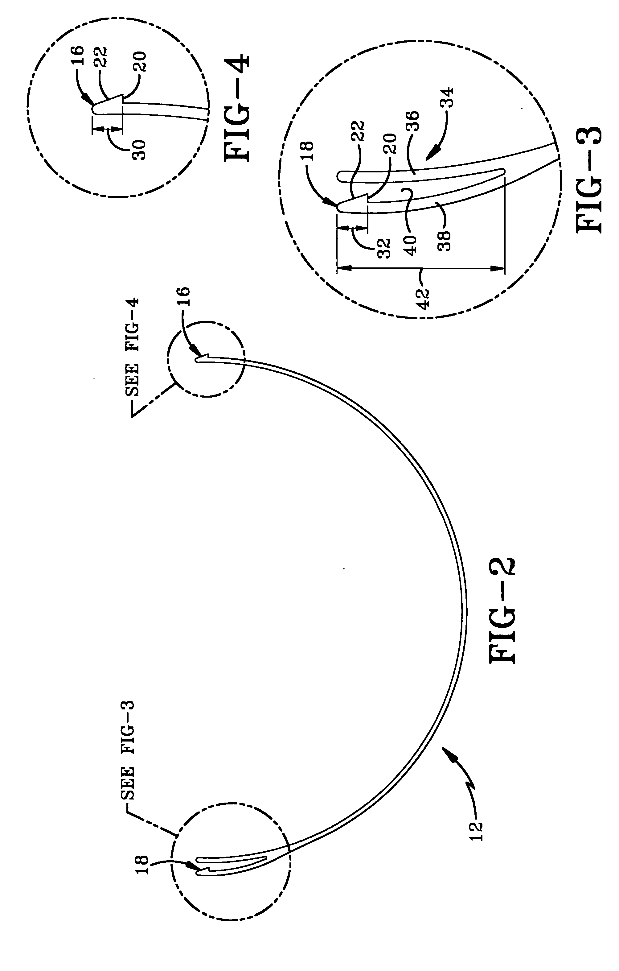
[0030] A duct section made in accordance with the concepts of the present invention is indicated generally by the numeral 10 in the accompanying drawings. Duct section 10 is formed by interlocking at least two duct portions 12 that interlock at two longitudinal joints 14 to form duct section 10. Each longitudinal joint includes a male tooth 16 and a female tooth 18 that lock together when portions 12 are connected to form duct section 10. Each tooth 16 and 18 defines a locking surface 20 and an angled surface 22 that allow teeth 16 and 18 to cooperate to fit together and then lock portions 12 in place. When only two portions 12 are used to form duct section 10, locking surfaces 20 are 180° apart from each other as depicted in FIG. 2 such that a 360° opening is formed when two duct portions 12 are connected together as shown in FIG. 5. When more than two duct portions 12 are used to form duct section 10 as shown in FIG. 18, the angle between locking surfaces 20 on a single duct porti...


PUM


Abstract

An air duct section is formed from at least two longitudinal duct portions that snap together to form a hollow duct having a longitudinal direction. The duct section has a pair of ends that are adjustable between male and female configurations. The interlocking device used to connect the duct portions allows continuous adjustability between the first end and the second end of the duct section while minimizing air leaks and providing structural integrity to the duct section.

Description

CROSS REFERENCE TO RELATED APPLICATION [0001] This application claims priority from U.S. Provisional Application Ser. No. 60 / 524,146 filed Nov. 21, 2003; the disclosure of which are incorporated by reference.BACKGROUND OF THE INVENTION [0002] 1. Technical Field [0003] The present invention generally relates to conduits and ducts and, more particularly, the types of conduits and ducts that are formed from multiple longitudinal pieces. Specifically, the present invention relates to a two piece air duct that is formed from two longitudinal pieces that snap together in a manner that allows the ends of the section to be adjusted between male and female configurations. [0004] 2. Background Information [0005] Air ducts in residential and commercial heating, ventilation, and air conditioning (HVAC) are typically formed from relatively thin sheet metal. The ducts may have round or rectangular cross sections and are typically purchased in formed sections of various lengths. Each section has a...

Claims


Application Information

Patent Timeline
Patent Type & Authority Applications(United States)
IPC IPC(8): F16L9/17F24F13/02
CPCF24F13/0209F16L9/17
Inventor SNYDER, DARRYL L.
Owner SNYDER NAT CORP
Why Eureka
Try Eureka