Air core motor-generator

Inactive Publication Date: 2009-04-28
REVOLUTION ELECTRIC MOTOR
View PDF25 Cites 27 Cited by
  • Summary
  • Abstract
  • Description
  • Claims
  • Application Information

AI Technical Summary

Benefits of technology

[0005]The invention provides an improved brushless motor-generator for converting between electrical and mechanical energy, affording high efficiency, long reliable operating life and is manufactured at low cost. The motor-generator includes a rotor and a stator that magnetically exerts torque upon the rotor. The rotor is constructed of a ferromagnetic tube that has a circumferential array of radially magnetized poles of alternating polarity around the circumferential array. The magnetic poles drive magnetic flux across an armature air gap. The stator includes a stationary air core armature that is located radially adjacent to the ferromagnetic tube and has multiple windings that are located in the air gap in a position to be intersected by the rotating flux field produced by the array of magnet poles. The armature windings utilize wire that is comprised of multiple individually insulated strands that are bundled together and sheathed in a

Problems solved by technology

This serve in many cases prevents strong adhesive bonding and would limit the strength of a conventional potted armature.
This additional wrapping of a band inside the air gap would normally be considered undesirable in conventional motor design because the band thickness would be thought to increase the required magnetic air gap thickness, which would normally be expected

Method used


Image

  • Air core motor-generator
  • Air core motor-generator
  • Air core motor-generator

Examples


Embodiment Construction

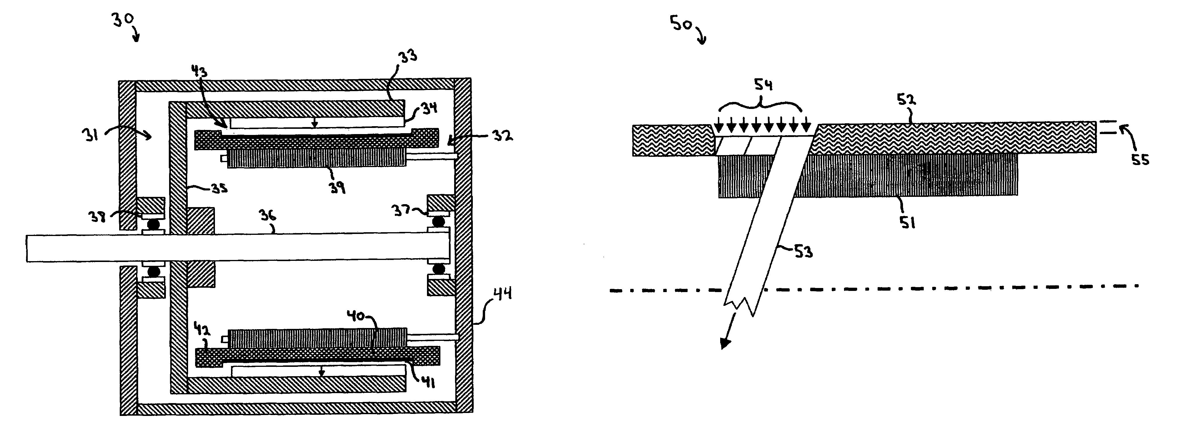
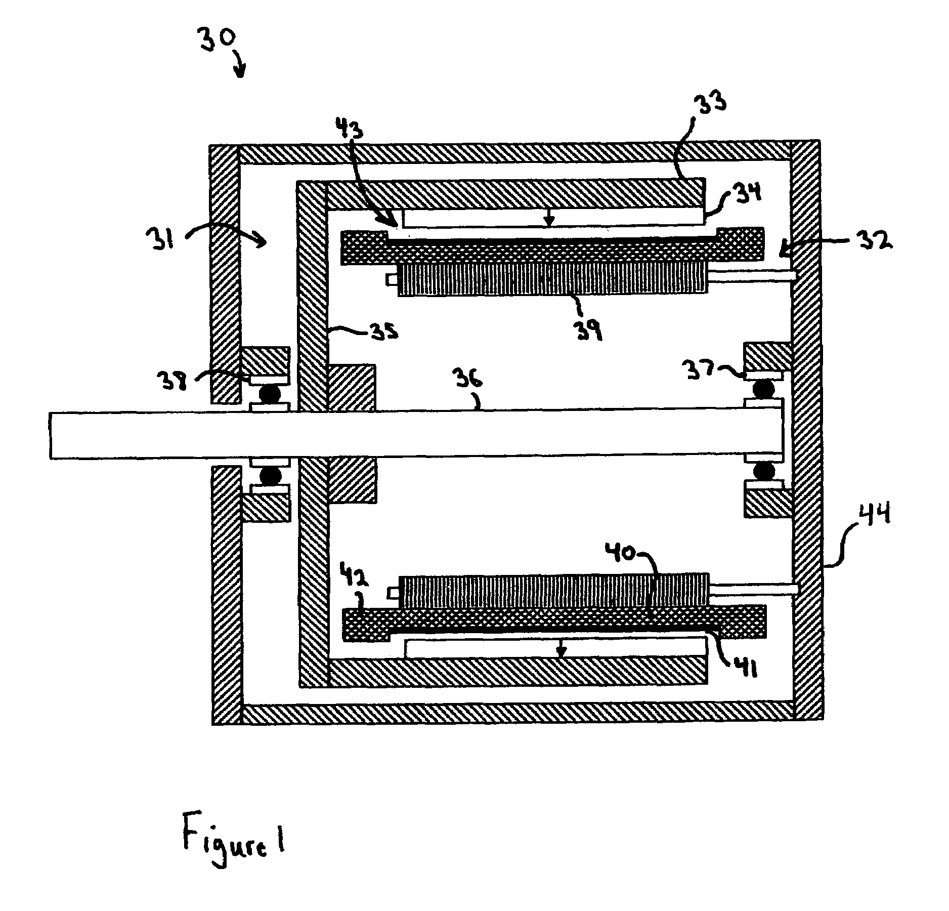
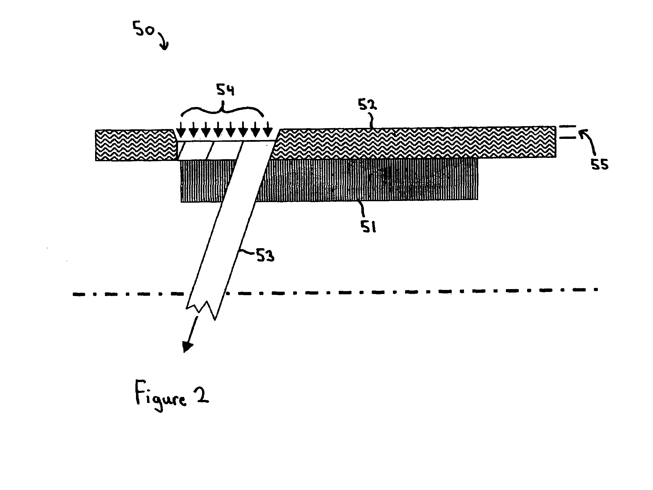
[0023]Turning to the drawings, wherein like reference characters designate identical or corresponding parts, FIG. 1 shows an improved motor-generator 30 having a rotor 31 mounted for rotation relative to a stationary stator 32. The rotor 31 includes an outer steel tube 33 that has a circumferential array of radially polarized magnetic poles 34 of circumferentially alternating polarity, as shown more clearly in FIG. 3. The poles 34 can include magnets and consequence steel poles or more preferably are all magnets for maximum flux production. A hub plate 35 attaches the steel tube 33 to a central shaft 36 that is journalled for rotation in bearings 37, 38. The magnetic poles 34 drive magnetic flux radially across a radial magnetic air gap 43 defined between the rotor 33 and a stationary back iron 39 attached to a stationary housing 44. The back iron 39 is preferably constructed of ferromagnetic material with magnetic induced loss mitigating properties. One preferred construction for t...


PUM


Abstract

A brushless motor-generator includes a rotor having a ferromagnetic tube with radially polarized, alternating polarity permanent magnet poles, and an air core armature that magnetically exerts torque upon the rotor. The magnetic poles drive magnetic flux across a radial magnetic air gap inside of the tube and through windings of the armature that are located in the air gap. The windings utilize wire that is comprised of multiple individually insulated strands that are bundled together and sheathed in an outer electrically insulating serve that separates adjacent windings and provides a higher dielectric breakdown strength than the insulation on the individually insulated strands. A thin circumferentially tensioned band is wrapped around the outer diameter of the axially traversing portions of the windings where located inside the magnetic air gap, imparting radial compression and structural integrity to the windings and increasing the circumferential structural strength of the air core armature for torque production.

Description

[0001]This invention pertains to motor-generators for converting between electrical and mechanical energy, and more importantly to a brushless, radial gap, motor-generator of specialized construction for providing increased efficiency and power capability with more reliable and lower cost construction.BACKGROUND OF THE INVENTION[0002]There is a desire for low cost electrical machines for converting between electrical and mechanical energy that have both high efficiency and high performance capability. Unfortunately, current devices tend to suffer from one or more of a number of deficiencies that include low efficiency, low performance or speed capability, complex and expensive construction and poor heat transfer. One factor contributing to both the losses and complexity of many machines is the required use of laminations. Laminations reduce eddy current losses and the materials can be chosen for low hysteresis losses. However, the lamination losses still tend be about 3-4% or higher...

Claims


Application Information

Patent Timeline
IPC IPC(8): H02K1/00H02K3/00
CPCH02K3/47H02K21/14H02K21/22
Inventor GABRYS, CHRISTOPHER W.
Owner REVOLUTION ELECTRIC MOTOR
Why Eureka
Try Eureka