Power splitting vehicle drive system

a technology for driving systems and power splitting vehicles, applied in electric propulsion mounting, transportation and packaging, gearing, etc., can solve the problems of increasing the cost and weight of the work vehicl

Active Publication Date: 2005-05-26
OSHKOSH CORPORATION
View PDF10 Cites 96 Cited by
  • Summary
  • Abstract
  • Description
  • Claims
  • Application Information

AI Technical Summary

Problems solved by technology

Such multiple components increase the cost and the weight of the work vehicle.

Method used


Image

  • Power splitting vehicle drive system
  • Power splitting vehicle drive system
  • Power splitting vehicle drive system

Examples


Embodiment Construction

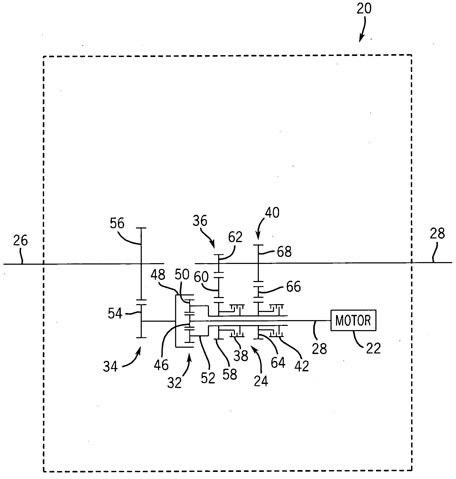
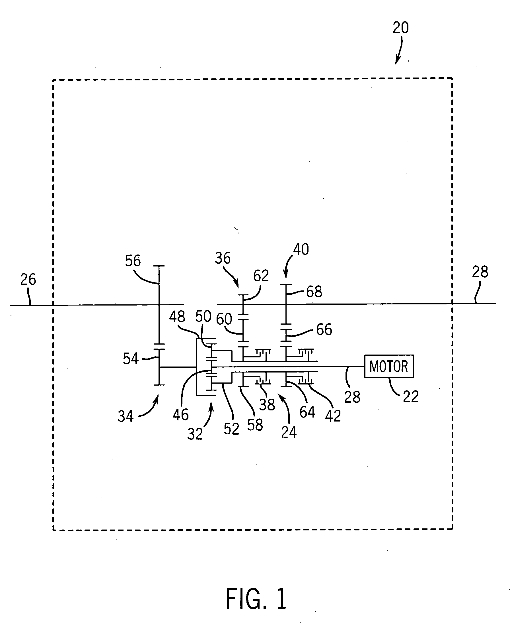
[0021]FIG. 1 is a schematic illustration of a drive system 20 which generally includes prime mover 22, distribution system 24, output shaft 26 and output shaft 28. Prime mover 22 generally comprises a source of rotational mechanical energy which is derived from a stored energy source. Examples include, but are not limited to, an internal combustion gas-powered engine, a diesel engine, turbines, fuel cell driven motors, an electric motor or any other type of motor capable of providing rotation of mechanical energy to the prime mover output shaft 28 which is coupled to distribution system 24.

[0022] Distribution system 24 is operably coupled between motor 22 and output shafts 26 and 28. For purposes of this disclosure, the term “coupled” means the joining of two members directly or indirectly to one another. Such joining may be stationary in nature or movable in nature. Such joining may be achieved with the two members or the two members and any additional intermediate members being i...


PUM


Abstract

A vehicle includes a prime mover, a first output shaft, a second output shaft and a planetary gear assembly. The planetary gear assembly includes a sun gear, a ring gear and a plurality of planetary gears supported between the ring gear and the sun gear by a carrier. One of the sun gear and the ring gear is coupled to the prime mover. The other of the ring gear and the sun gear is coupled to the first output shaft. The first carrier is coupled to the second output shaft.

Description

CROSS REFERENCE TO RELATED APPLICATIONS [0001] The present application is related to co-pending U.S. patent application Ser. No. 10 / 137,585 filed on May 2, 2002 by Jon J. Morrow and Christopher K. Yakes and entitled HYBRID VEHICLE WITH COMBUSTION ENGINE / ELECTRIC MOTOR GUIDE, the full disclosure of which is hereby incorporated by reference.FIELD OF THE INVENTION [0002] The present invention generally relates to a drive system for a vehicle. In particular, the present invention relates to a work vehicle splitting power between a first output shaft and a second output shaft. BACKGROUND OF THE INVENTION [0003] Most of today's heavy work vehicles require all-wheel drive. Such all-wheel drive vehicles typically include standard vehicle differential for splitting power between multiple axles of the vehicle and a distinct transfer case for providing speed reduction to achieve the generally high required torques. Such multiple components increase the cost and the weight of the work vehicle. ...

Claims


Application Information

Patent Timeline
Patent Type & Authority Applications(United States)
IPC IPC(8): B60K1/02B60K6/365B60K6/387B60K6/46B60K6/48B60K6/52B60K17/04B60K17/356F16H3/72
CPCB60K1/02Y02T10/6239B60K6/387B60K6/445B60K6/46B60K6/48B60K6/52B60K17/043B60K17/356B60Y2200/14F16H3/728Y02T10/6217Y02T10/6221Y02T10/6265B60K6/365B60K17/36B60K2001/001Y02T10/62
Inventor MORROW, JON J.
Owner OSHKOSH CORPORATION
Why Eureka
Try Eureka