Tool box with a logo plate thereon

a tool box and logo technology, applied in the field of tool boxes, can solve the problem of ink color fade and other problems

Inactive Publication Date: 2005-05-26
STANLEY CHIRO INT
View PDF32 Cites 18 Cited by
  • Summary
  • Abstract
  • Description
  • Claims
  • Application Information

AI Technical Summary

Benefits of technology

[0008] An object of the present invention is to provide a tool box that has a logo plate thereon. The logo plate can be mounte...

Problems solved by technology

In addition, the color of the ...

Method used


Image

  • Tool box with a logo plate thereon
  • Tool box with a logo plate thereon
  • Tool box with a logo plate thereon

Examples


Embodiment Construction

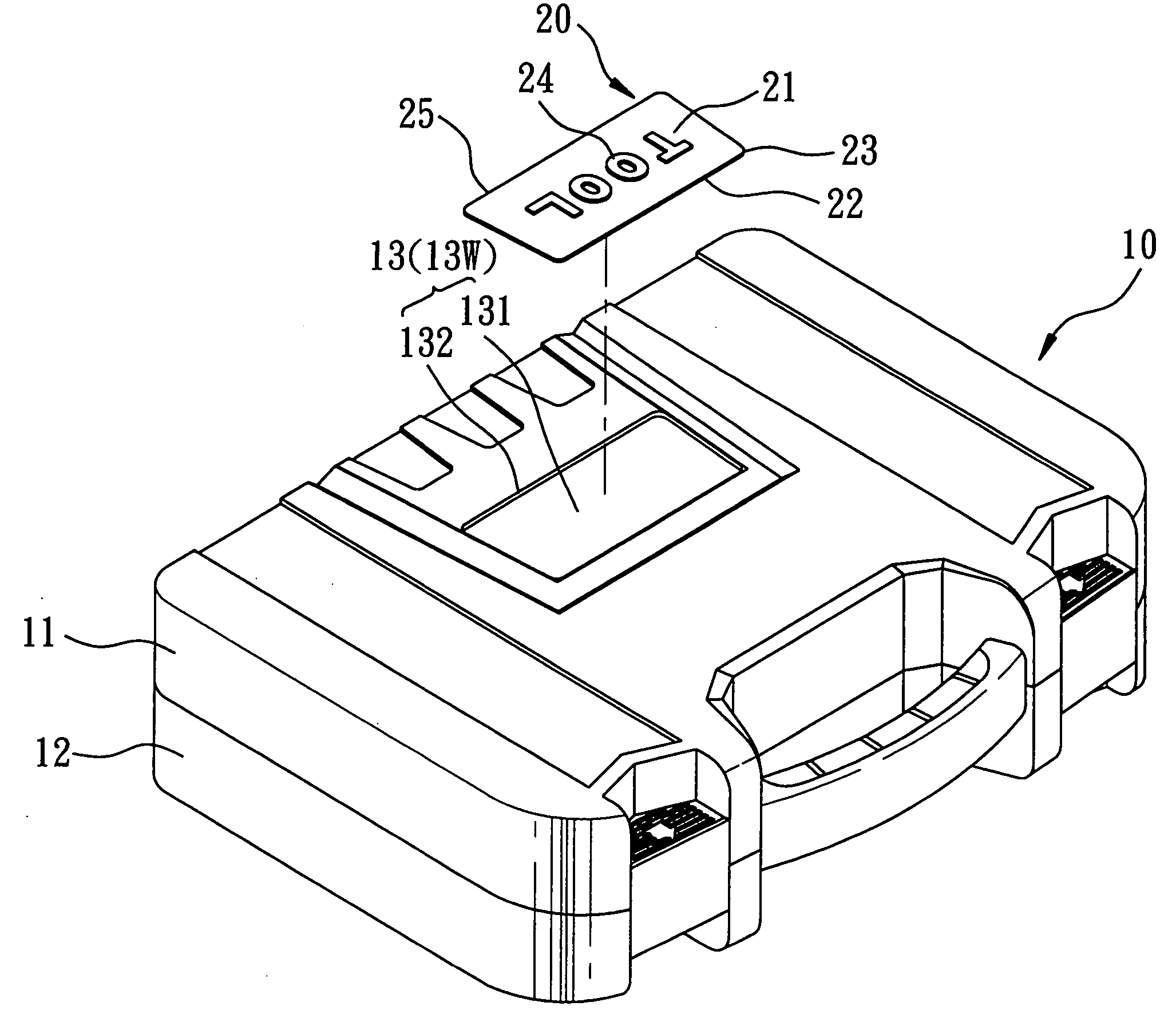
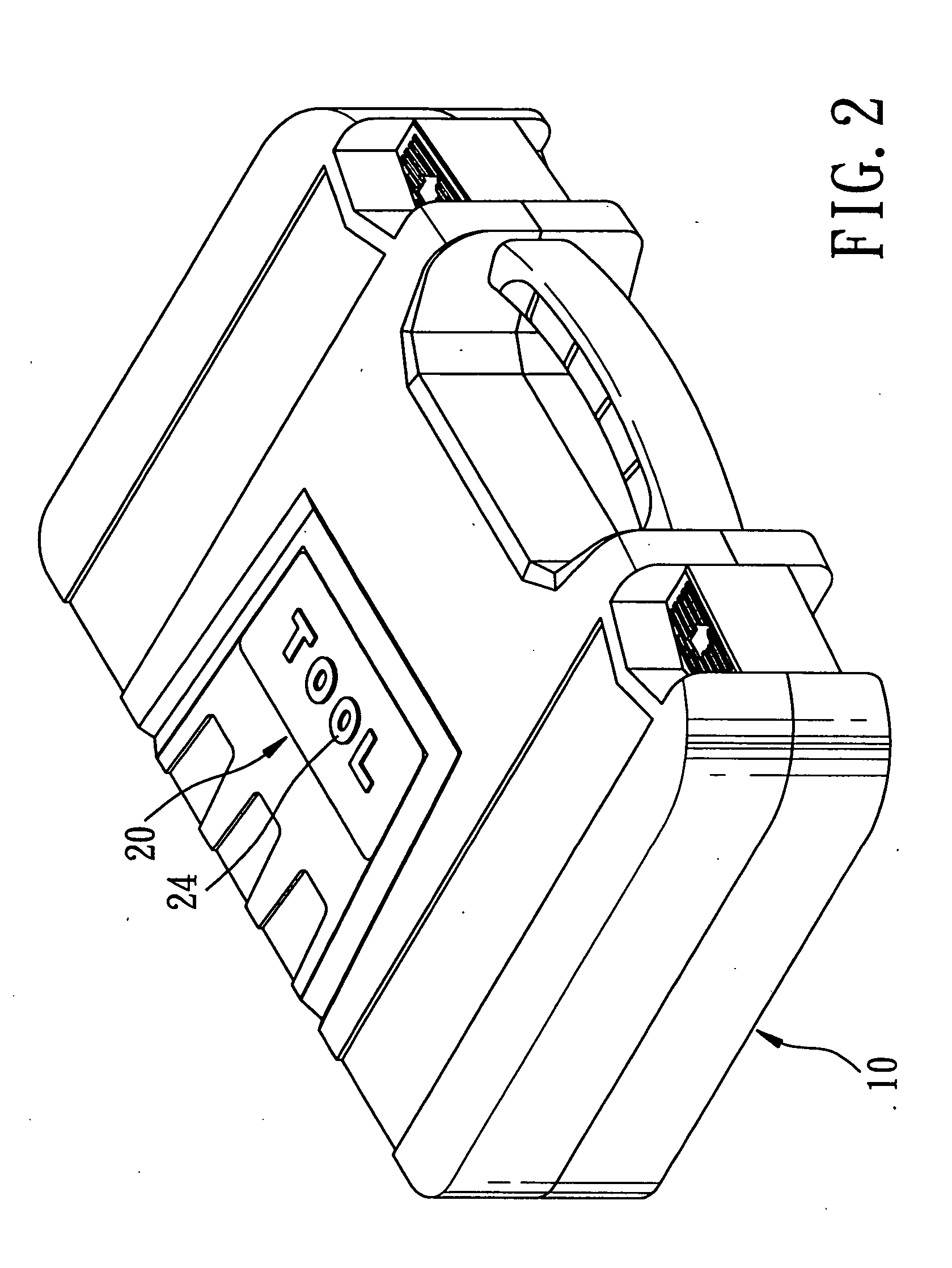
[0018] Referring to FIGS. 2 to 5, the first preferred embodiment of a tool box according to the present invention is shown to include a molded box body 10 and a logo plate 20.

[0019] As illustrated, the molded box body 10 includes pivotally connected upper and lower box halves 11, 12. The upper box half 11 has an outer face formed with a plate-receiving recess 13 confined by a recess-defining wall 13W that has a bottom wall portion 131 and a peripheral wall portion 132 extending from the bottom wall portion 131 to the outer face of the upper box half 11.

[0020] The logo plate 20 has an upper face 21 formed with a logo 24, a lower face 22 opposite to the upper face 21, and a peripheral side face 23 interconnecting the upper and lower faces 21, 22. The logo plate 20 is mounted securely within the plate-receiving recess 13 in the upper box half 11 through a shrink-fit process such that the logo plate 20 abuts against and is retained securely by the peripheral wall portion 132 of the re...


PUM


Abstract

A tool box includes a molded box body and a logo plate mounted securely within a recess formed in an outer face of the molded box body through a shrink-fit process. The recess is confined by a recess-defining wall that has a bottom wall portion and a peripheral wall portion extending from the bottom wall portion to the outer face. The logo plate is retained securely by the peripheral wall portion. The logo plate is fitted into the recess while the molded box body, which is formed through a hot molding process, is still in a hot softened state.

Description

BACKGROUND OF THE INVENTION [0001] 1. Field of the Invention [0002] The present invention relates to a tool box, more particularly to a tool box with a logo plate thereon. [0003] 2. Description of the Related Art [0004] Referring to FIG. 1, a conventional tool box is shown to include a molded box body 1 with a logo 1012 formed on an outer face 1011 of the box body 1. [0005] Drawbacks associated with forming the logo 1012 on the box body 1 are as follows: [0006] (1) In case a plurality of inserts corresponding to characters of the logo 1012 are used to form the logo 1012 on the box body 1 during molding of the tool box, relatively high precision is required to mount the inserts in the mold prior to molding, which is laborious. [0007] (2) In case a printing technique is employed to form the logo 1012 on the molded box body 1, the molded box body 1 must undergo a flame treating process to oxidate the outer face 1011 of the molded box body 1 so as to permit firm adhesion of printing ink...

Claims


Application Information

Patent Timeline
IPC IPC(8): A45C13/08A45C13/42B25H3/02G09F23/00
CPCA45C13/08A45C13/42G09F23/00B25H3/02A45C2005/037
Inventor HUANG, STEVE
Owner STANLEY CHIRO INT
Why Eureka
Try Eureka