Image forming device including mechanism to lock cover

a technology of forming device and locking mechanism, which is applied in the direction of thin material processing, printing, article separation, etc., can solve the problems of excessive load on the hinge, and achieve the effect of reducing the rattle of the cover body

Inactive Publication Date: 2005-05-26
BROTHER KOGYO KK
View PDF17 Cites 10 Cited by
  • Summary
  • Abstract
  • Description
  • Claims
  • Application Information

AI Technical Summary

Benefits of technology

[0009] In the view of foregoing, it is an object of the present invention to overcome the above problems, and also to provide an image forming device which is reduced in rattle of a cover body and which prevents the cover body from accidentally opening when a user lifts up the device by grabbing the cover body.

Problems solved by technology

Also, if the user lifts up the image forming device by grabbing the cover body 520 opened with the main body 510 hanging therefrom via the hinge, an excessive load is exerted on the hinge.
This may sever the main body 510 from the cover body 520, causing a danger that the severed main body 510 drops onto the user to cause an injury.

Method used


Image

  • Image forming device including mechanism to lock cover
  • Image forming device including mechanism to lock cover
  • Image forming device including mechanism to lock cover

Examples


second embodiment

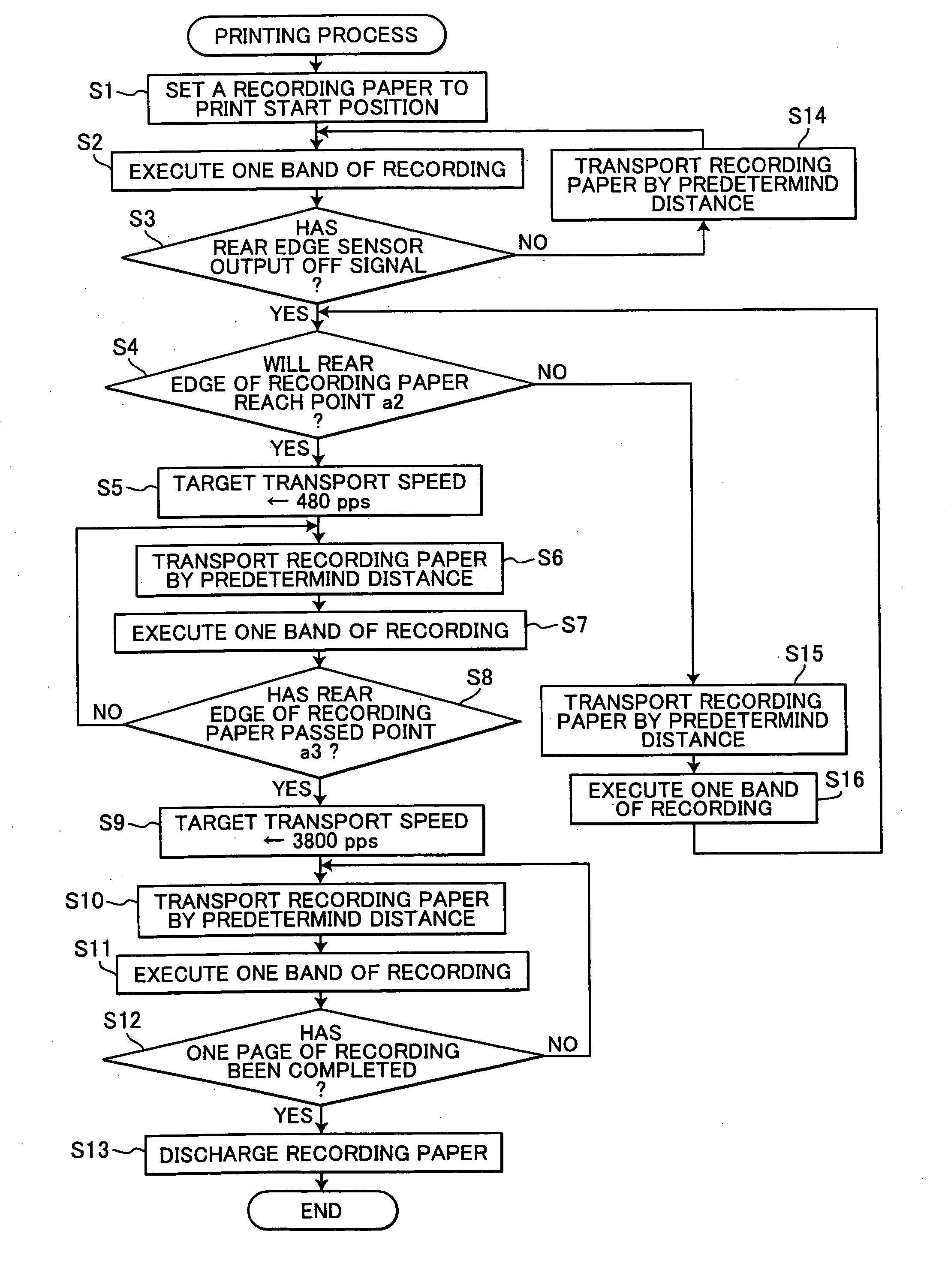
[0105] As described above, according to the printing process of the second embodiment, the reduced speed of 480 pps is maintained only for a minimum time duration, and so the printing process can be performed efficiently.

[0106] Since the reduced speed of 480 pps is maintained only for a minimum time duration in the second embodiment, the target rotation speed may be changed from 480 pps to 3,800 pps in the middle of transport operation for a predetermined distance. In such cases, the rotation speed is accelerated from 480 pps to 3,800 pps with the acceleration smaller than the normal acceleration in the similar manner as in the first embodiment.

third embodiment

[0107] Next, a printing process according to the present invention will be described with reference to the flowchart of FIG. 15.

[0108] The ink-jet head 109 and rollers, such as the transport roller 101, are varied in size and shape due to tolerance in their manufacture. Accordingly, the transport amount with printing varies among products. This is one of the factors that lower the printing quality. The printing quality is also influenced by the type of recording sheet, such as material and thickness of the recording sheet.

[0109] In the first and second embodiments, the multi-function peripheral device 1 performs the printing process without taking into account the variation among the products. In the third embodiment, correction values regarding a sheet transport specific to the multi-function peripheral device 1 are stored in the setting value memory 124, and a sheet transport amount is corrected based on those correction values. Also, when transporting a recording sheet by the fe...

first embodiment

[0112] Components identical with those of the multi-function peripheral device 1 in the first embodiment are denoted by the same reference numerals and explanations thereof will be omitted.

[0113]FIG. 15 shows the flowchart representing the printing process according to the present embodiment. In this printing process, first, it is determined whether or not a recording sheet to use is a coated paper (S41). If so (S41: YES), then the process proceeds to S45, where a correction value T is set to 1, and the process proceeds to S46. If not (S41: NO), then it is determined whether or not the recording sheet is a glossy paper (S42). If so (S43: YES), then the correction value T is set to 2 (S43), and the process proceeds to S46. If not (S42: NO), then this means that the recording sheet is a normal sheet, and the correction value T is set to 0 (S44). Then, the process proceeds to S46. Note that OHP sheet could be also used. In this case, the correction value T is the same as for the glossy...


PUM


Abstract

When a cover body at a closing position is pulled up with respect to a main body, then a lock lever attached to the cover body abuts against a hook body of the main body, regulating a rattle of the cover body with respect to the main body. When a user lifts up a multi-function peripheral device by grabbing the lock lever, the lock lever comes into engagement with the hook body, thereby preventing the lock lever from opening.

Description

BACKGROUND OF THE INVENTION [0001] 1. Field of the Invention [0002] The present invention relates to an image forming device, and more specifically to an image forming device which is reduced in rattle of a cover body with respect to a main body in a vertical direction and which prevents the cover body from accidentally opening when the image forming device is lifted up by grabbing the cover body. [0003] 2. Description of the Related Art [0004] There has been provided an image forming device that includes a main body provided with a printing unit for printing images on a recording sheet and a cover body provided with a reading unit for reading images from original documents. The cover body is disposed above and pivotally supported on the main body via a hinge so that cover body can move to its opening position by pivoting upward and to its closing position by pivoting downward. [0005]FIG. 17 is a magnified partial view showing a main body 510 and a cover body 520 of a conventional i...

Claims


Application Information

Patent Timeline
Patent Type & Authority Applications(United States)
IPC IPC(8): B41J29/13
CPCB41J29/13
Inventor SAKAKIBARA, AKIHIROMORIBE, MASATOSUGIURA, TOSHIO
Owner BROTHER KOGYO KK
Why Eureka
Try Eureka