
Image forming apparatus and image forming method

a technology of image forming apparatus and forming method, which is applied in the direction of electrographic process apparatus, instruments, developers, etc., can solve the problems of insufficient change of recycled toner, insufficient charging, and often degraded toner, etc., and achieve the effect of satisfactorily developing an imag

Active Publication Date: 2005-05-26
KK TOSHIBA +1
View PDF4 Cites 16 Cited by
  • Summary
  • Abstract
  • Description
  • Claims
  • Application Information

AI Technical Summary

Benefits of technology

[0012] The present invention has been made in order to solve the above problems. Accordingly, it is an object of an aspect of the present invention is to provide an image forming apparatus and an image forming method, which can develop an image satisfactorily by chagrining sufficiently even with recycled toner.
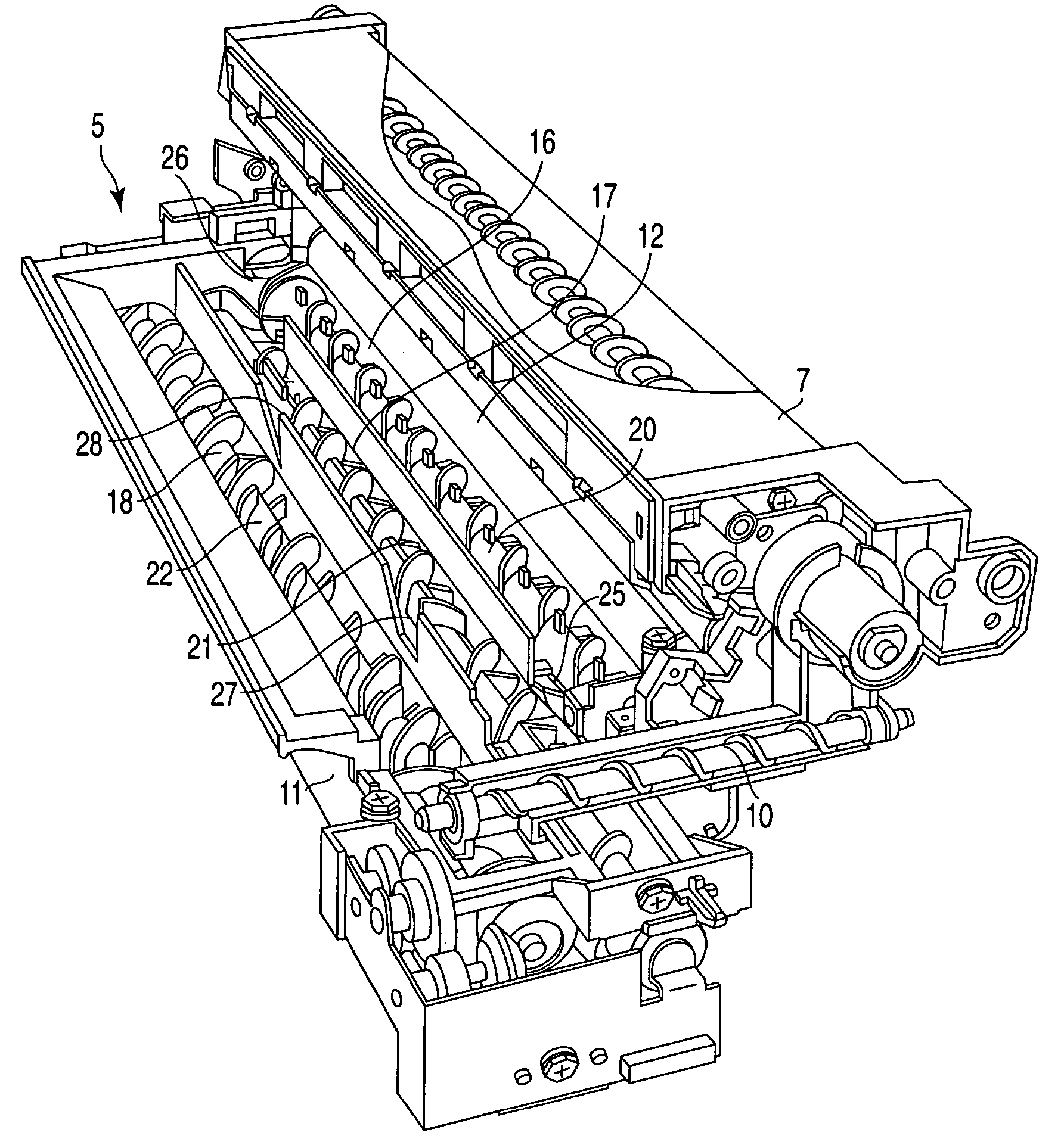
[0014] According to another aspect of the invention, there is provided an image forming method, which supplies a two-component developer composed of toner and carrier to an electrostatic latent image formed on an image holding element by a developing roller in a developer reservoir to make the latent image as a developer image, transfers the developer image to a material to be transferred, eliminates the toner remained on the image holding element and collects the toner to the developer reservoir by a collection device, and replenishes toner to the developer reservoir by a toner replenish device, comprising dividing the inside of the developer reservoir into first to third chambers substantially parallel to the developing roller by the first and second partition members; forming a first connecting opening in the first partition member, and connecting the first and second chambers; forming a second connecting opening in the second partition member, and connecting the second and third chambers; supplying the developer in the first chamber to the developing roller by a first stirring and carrying member by stirring and carrying in a first direction from one end side to the other end side of the chamber; feeding the developer replenished from the replenish device and toner fed from the first chamber to the second chamber through the first connecting opening to one end side of the first stirring and carrying member by a second stirring and carrying member by stirring and carrying in a second direction reverse to the first direction; and feeding the toner collected by the collection device to one end side of the first stirring and carrying member by a third stirring and carrying member by stirring and carrying in the second direction at a speed lower than the second stirring and carrying member.

Problems solved by technology

However, in the prior art, as replenished toner and recycled toner are fed to one end side of the second mixer, in which they are mixed, stirred and carried, the replenished fresh toner is sufficiently charged, but the recycled toner is not sufficiently changed.
But, the recycled toner is often degraded, and cannot be sufficiently charged at the stirring and carrying speed of the second motor.
Thus, good development is not expected.

Method used


Image

  • Image forming apparatus and image forming method
  • Image forming apparatus and image forming method
  • Image forming apparatus and image forming method

Examples


Embodiment Construction

[0030] The present invention will be explained in detail hereinafter with reference to the embodiments shown in the accompanied drawings.

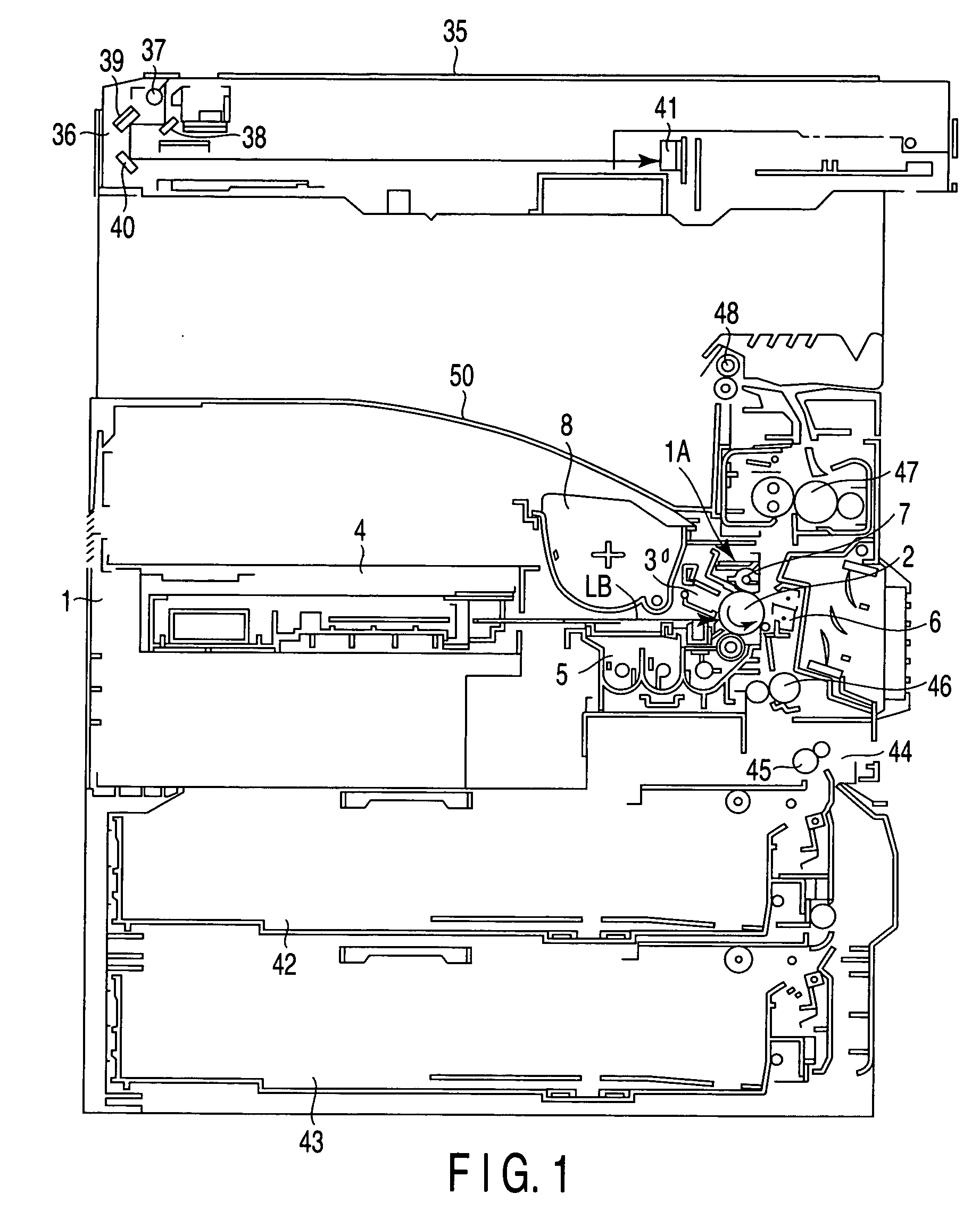
[0031]FIG. 1 shows schematically the internal structure of an electrophotographic copying machine as an image forming apparatus according to an embodiment of the present invention.

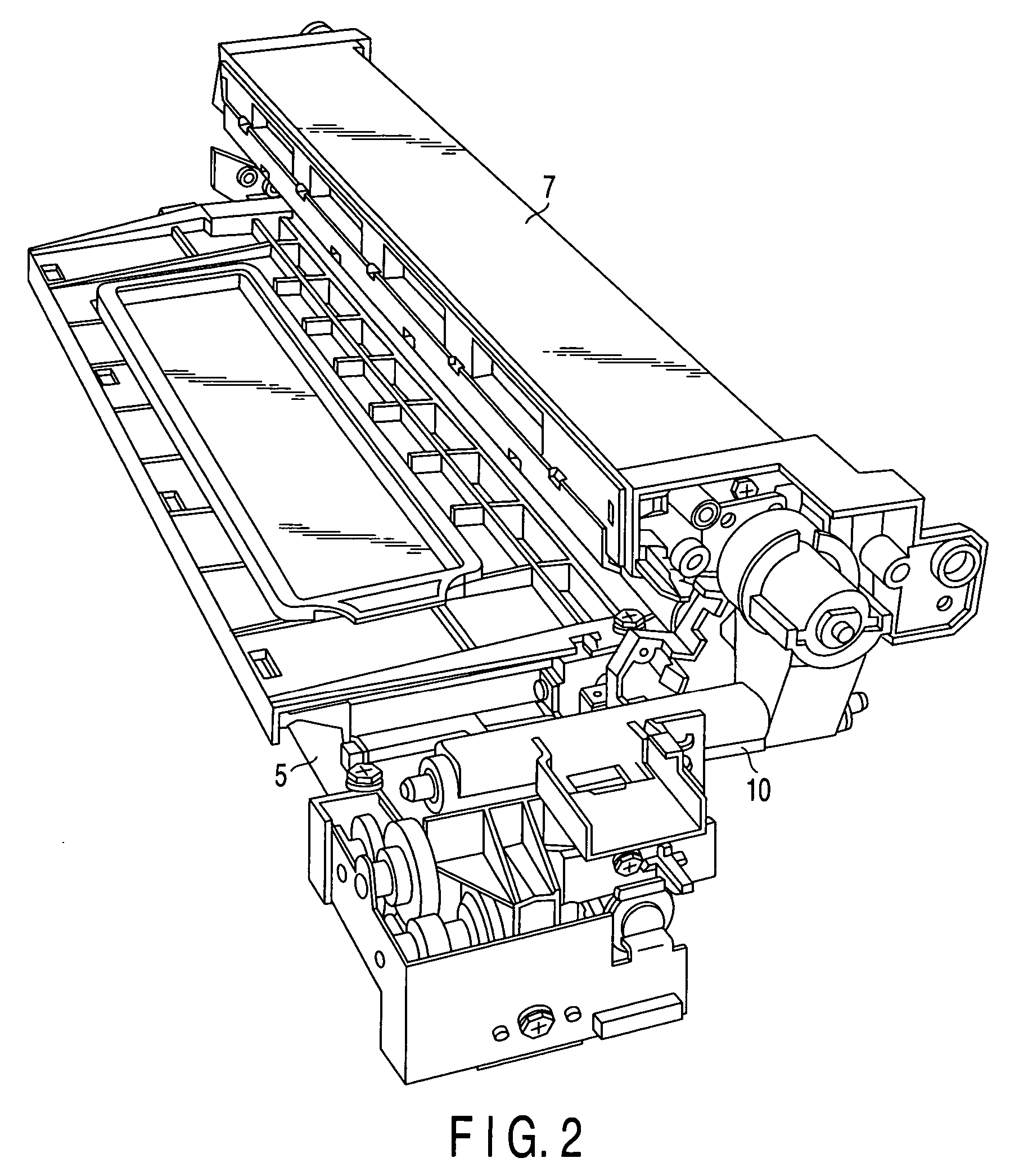
[0032] In the drawing, a reference numeral 1 denotes a main unit of the copying machine. An image forming unit 1A is provided in one side of the middle of the main unit 1 of the copying machine. The image forming unit 1A has a photoconductor drum 2 as an image holding element rotatable in the arrow direction. A charger 3 to charge the surface of the photoconductive drum 2, a laser unit 4 to form a static latent image on the surface of the photoconductor drum 2, a developing unit 5 to develop the static latent image with toner on the photoconductor drum 2, a transfer charger 6 as a transfer device to transfer the toner image on the photoconductive drum 2 to a paper sheet...


PUM


Abstract

A developing unit has first and second partition walls and which divide the inside of a developer reservoir into first to third chambers parallel to the developing roller, and first to third mixers which are disposed in the first to third chambers. The first mixer supplies developer to the developing roller by stirring and carrying from one end side to the other end side. The second mixer feeds by stirring and carrying the toner replenished from a replenish device and developer fed from the first chamber to one end side of the first mixer. The third mixer feeds the toner collected from a collection mechanism to one end side of the first mixer by stirring and carrying at a speed lower than the second mixer.

Description

CROSS-REFERENCE TO RELATED APPLICATIONS [0001] This application is based upon and claims the benefit of priority from prior Japanese Patent Applications No. 2003-393060, filed Nov. 21, 2003; and No. 2004-210540, filed Jul. 16, 2004, the entire contents of both of which are incorporated herein by reference. BACKGROUND OF THE INVENTION [0002] 1. Field of the Invention [0003] The present invention relates to an image forming apparatus which is applied as an electrophotographic copying machine, and an image forming method. [0004] 2. Description of the Related Art [0005] In this kind of image forming apparatus, an electrostatic latent image is formed on a photoconductor drum as an image holding element, and the latent image is developed as a toner image by a developing unit. The toner image is transferred to a paper sheet in a transfer unit. The toner remained on the photoconductor drum at the time of transfer is eliminated by a cleaning unit. [0006] In a certain image forming apparatus,...

Claims


Application Information

Patent Timeline
Patent Type & Authority Applications(United States)
IPC IPC(8): G03G9/10G03G15/08G03G21/10
CPCG03G21/10G03G2215/0822G03G2215/0819G03G2215/0607
Inventor AMANO, TAKAFUMINOMURA, SUSUMUKATO, TETSUOIKEDA, TAKASHIKOBAYASHI, YUKIE
Owner KK TOSHIBA
Learn More