Charging member having an elastic foam member including cell portions whose gap ratio is 5% to 50%, charging apparatus, process cartridge, and image forming apparatus having such charging member

a charging member and foam member technology, applied in the direction of charging apparatus, corona discharge, instruments, etc., can solve the problems of inability to get around the problems, in principle, the inability of the electrical-discharge-based charging mechanism to leave any byproduct, and the inability to discharge byproducts, etc., to achieve satisfactory charging performance and satisfactory images

Inactive Publication Date: 2005-06-07
CANON KK
View PDF9 Cites 11 Cited by
  • Summary
  • Abstract
  • Description
  • Claims
  • Application Information

AI Technical Summary

Benefits of technology

[0054]The primary object of the present invention is to solve the above-described problems, and provide a charging member, a charging apparatus, an image forming apparatus, and a process cartridge, which are capable of assuring satisfactory charging performance, and the production of satisfactory images.
[0055]Another object of the present invention is to provide a charging member, a charging apparatus, an image forming apparatus, and a process cartridge, which are capable of preventing foreign substances, such as paper dust, from accumulating on and in the foamed portion of the charging member.
[0056]Another object of the present invention is to provide a charging member, a charging apparatus, an image forming apparatus, and a process cartridge, which are superior in particle retention.

Problems solved by technology

Further, in the case of the electrical-discharge-based charging mechanism, electrical discharge leaves byproducts.
However, it is impossible, in principle, for the electrical-discharge-based charging mechanism not to leave any byproduct.
Hence, it is impossible to get around the problems resulting from active ions such as ozone that are generated with this mechanism.
It is, however, a mechanism which directly charges an object; its charging efficiency is greatly affected by the state of contact between a contact charging member and the object to be charged.
Thus, when a charge roller is used for a contact charging mechanism, it cannot be avoided that the object to be charged is non-uniformly charged due to the loss in the absolute charging performance of the charge roller, deterioration in the state of contact between the charge roller and the object to be charged, irregularities in the surface of the charge roller, and / or foreign deposits on the peripheral surface of a photoconductive member.
With the use of a DC based charging method, however, it was difficult to charge a photoconductive member to a predetermined potential level due to the following reasons.
Further, the AC voltage applied to more uniformly charge the photoconductive member created new problems distinctive to AC voltage.
Further, the peripheral surface of the photoconductive drum was deteriorated by electrical discharge.
However, the fiber density of 100 fibers / mm2 is not high enough to realize a state of contact sufficient to satisfactorily uniformly charge the photoconductive member with the use of a fur-brush-based charging method.
In other words, in order to satisfactorily uniformly charge the photoconductive member with the use of a fur-brush-based charging method, the difference in peripheral velocity between the peripheral surface of the photoconductive drum and the surface of the fur brush portion must be so large that it is virtually impossible to mechanically realize.
In other words, the provision of such a difference in peripheral velocity between the peripheral surface of the photoconductive drum and the surface of the fur-brush portion of the fur-brush-based charging device is unrealistic.
However, the magnetic-brush-based charging method has its own weakness, and suffers from problems different from those of the preceding methods.
For example, it is complicated in structure.
Further, there is a tendency that a certain amount of the electrically conductive magnetic particles fall out of the magnetic-brush portion and adhere to the photoconductive drum.
Therefore, there is a problem regarding how to satisfactorily charge a photoconductive drum with the use of a contact charging method as a means for charging a photoconductive drum while toner, which is electrically insulative, is in the interface between the photoconductive drum and contact charging member.
However, the employment of a toner-recycling system complicates the apparatus structure, and also creates a serious problem in that the electrically conductive magnetic particles forming the magnetic-brush portion fall out.
With the above described simple setup that the charge roller is rotated by the rotation of the photoconductive drum, it is impossible to realize such a state of contact.
However, in the case of the charge roller, or a contact charging member formed of elastic material, there is a large amount of friction between the contact charging member and the object to be charged, making it impossible to rotate the contact charging member while maintaining the substantial amount of velocity difference between the surfaces of the contact charging member and the object to be charged.
Also, forcing the contact charging member to rotate under such a condition resulted in a problem that the surfaces of the contact charging member and the object to be charged were shaved.
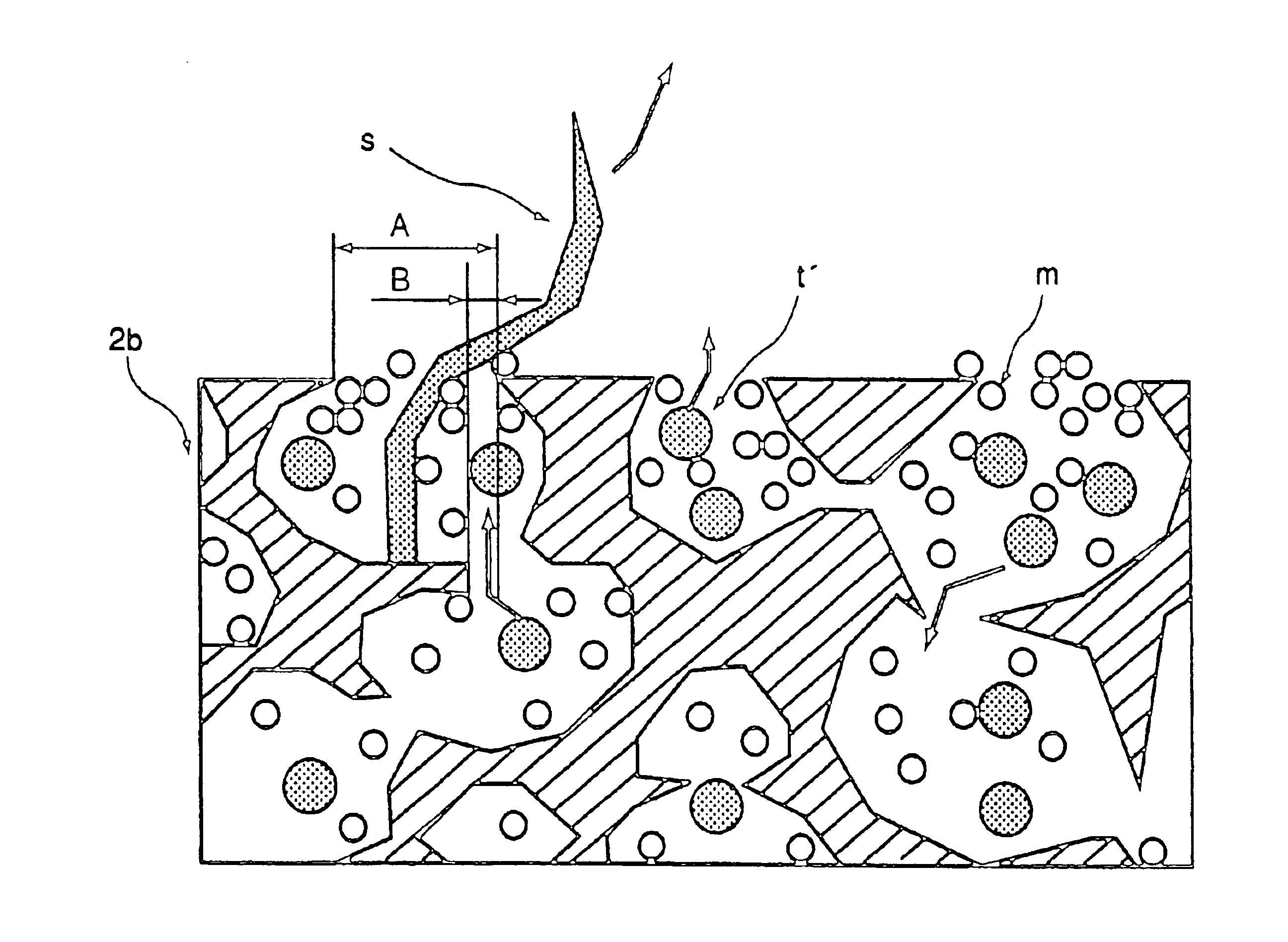
However, when the above-described charging apparatus is employed by a cleanerless image forming apparatus, that is, an image forming apparatus which does not have a dedicated cleaner, and a sponge roller, in which cells are interconnected, is employed as the charging member for the charging apparatus, the following problem occurs; as the cumulative number of copies increases, the cumulative amount of the fibrous paper dust which deposits on the sponge roller also increases, and the transfer residual toner particles agglomerate around the paper dust particles, causing the charging member to become unsatisfactory in charging performance.
On the other hand, when a sponge roller in which cells are discrete is used as the charging member of a cleanerless image forming apparatus, the following problem, which is different from the above-described one, occurs.
That is, the transfer residual toner particles are quickly expelled onto the peripheral surface of a photoconductive drum, because such a sponge roller is inferior in particle retention, and therefore, fails to temporarily retain the transfer residual toner particles.
In such a case, the developing device fails to recover all the transfer residual toner particles from the peripheral surface of the photoconductive drum, and the particles which the developing apparatus failed to recover, in other words, the particles which were left on the peripheral surface of the photoconductive drum, are transferred onto a transfer medium, causing the background portion of an image to appear slightly foggy.

Method used


Image

  • Charging member having an elastic foam member including cell portions whose gap ratio is 5% to 50%, charging apparatus, process cartridge, and image forming apparatus having such charging member
  • Charging member having an elastic foam member including cell portions whose gap ratio is 5% to 50%, charging apparatus, process cartridge, and image forming apparatus having such charging member
  • Charging member having an elastic foam member including cell portions whose gap ratio is 5% to 50%, charging apparatus, process cartridge, and image forming apparatus having such charging member

Examples


embodiment 1

(Embodiment 1)

[0067]FIG. 1 is a schematic sectional view of a typical image forming apparatus equipped with a charging member or a contact charging apparatus in accordance with the present invention, for showing the general structure thereof.

[0068]The image forming apparatus in this embodiment is a laser printer (recording apparatus) which employs a transfer-type electrophotographic process, a process cartridge mounting / dismounting system, and a contact charging system.

(1) General Structure of Printer

[0069]Reference numeral 1 stands for an object (image bearing member) to be charged. In this embodiment, it is a negatively chargeable organic photoconductive member (negative photoconductive member, which hereinafter will be referred to as a photoconductive drum), which is in the form of a rotational drum with a diameter of 30 mm. This photoconductive drum 1 is rotationally driven at a peripheral velocity (process speed: PS; printing speed) of 50 mm / sec in the clockwise direction indic...


PUM

PropertyMeasurementUnit
pressureaaaaaaaaaa
particle sizesaaaaaaaaaa
volume resistivityaaaaaaaaaa

Abstract

A charging member for charging a member to be charged, includes an elastic foam member provided at a surface of the charging member. The elastic foam member includes a plurality of cell portions with wall portion defining the cell portions. The gaps connecting the cell portions have areas which are not less than 5% and not more than 50%, for respective cells.

Description

FIELD OF THE INVENTION AND RELATED ART[0001]The present invention relates to a charging member which is for charging an object such as an electrophotographic photoconductive member or an electrostatically recordable dielectric member, and has a foamed elastic portion, a charging apparatus comprising such a charging member, an image forming apparatus, such as a copying machine or a printer, employing such a charging apparatus, and a process cartridge employed by such an image forming apparatus.[0002]In the past, in the field of an image forming apparatus, such as an electrophotographic apparatus or an electrostatic recording apparatus, a corona based charging device (corona discharger) has been widely used as a charging apparatus for uniformly charging (or discharging) an image bearing member (object to be charged), such as an electrophotographic photoconductive member or an electrostatically recordable dielectric member, to predetermined polarity and potential level.[0003]A corona b...

Claims


Application Information

Patent Timeline
Patent Type & Authority Patents(United States)
IPC IPC(8): G03G15/02G03G5/147
CPCG03G15/0233G03G2221/183G03G15/02
Inventor HOSOKAWA, TAKAHIROISHIYAMA, HARUMICHIGONO, YASUNORIHIRABAYASHI, JUN
Owner CANON KK
Why Eureka
Try Eureka