Exercise device with elastic resistance

Inactive Publication Date: 2005-05-26
DOVNER EDWARD R
View PDF16 Cites 63 Cited by
  • Summary
  • Abstract
  • Description
  • Claims
  • Application Information

AI Technical Summary

Benefits of technology

[0013] In another aspect, the present invention provides a configuration using the latex tubing to span two handle portions tha

Problems solved by technology

Such devices eventually fail to challenge a user as the user's strength increases.
Materials such as solid rubber may provide so much resistance that that they become difficult to stretch through the desired range of motion, and thus are not adaptable for use by a wide variety of users with different strengths and needs for exercise.
Other exercise devices enable an adjustable level of resistance, but typically are associated with a commensurate increase i

Method used


Image

  • Exercise device with elastic resistance
  • Exercise device with elastic resistance
  • Exercise device with elastic resistance

Examples


Embodiment Construction

[0032] Preferred embodiments of the present invention will now be described with reference to the several figures of the drawing.

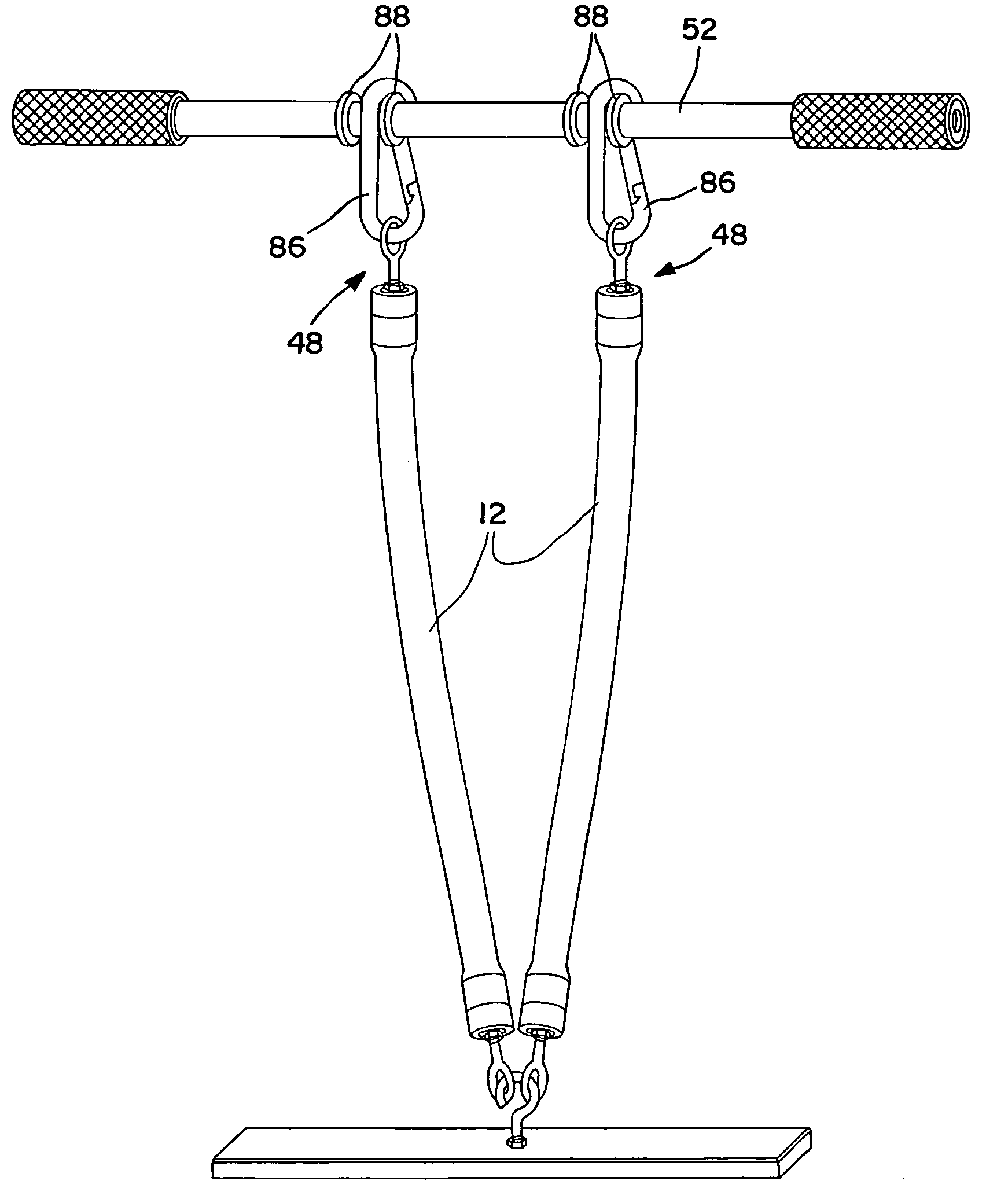
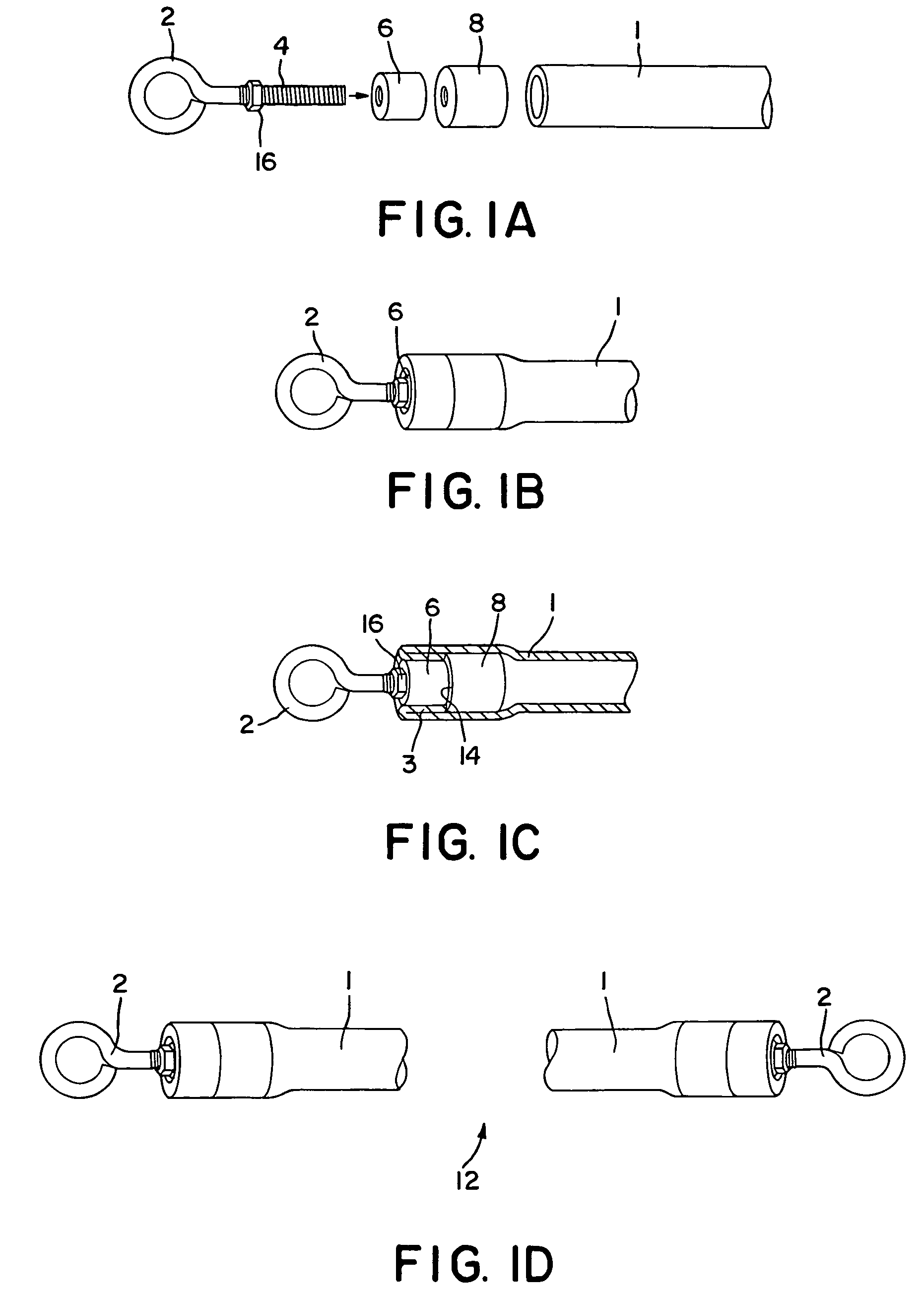
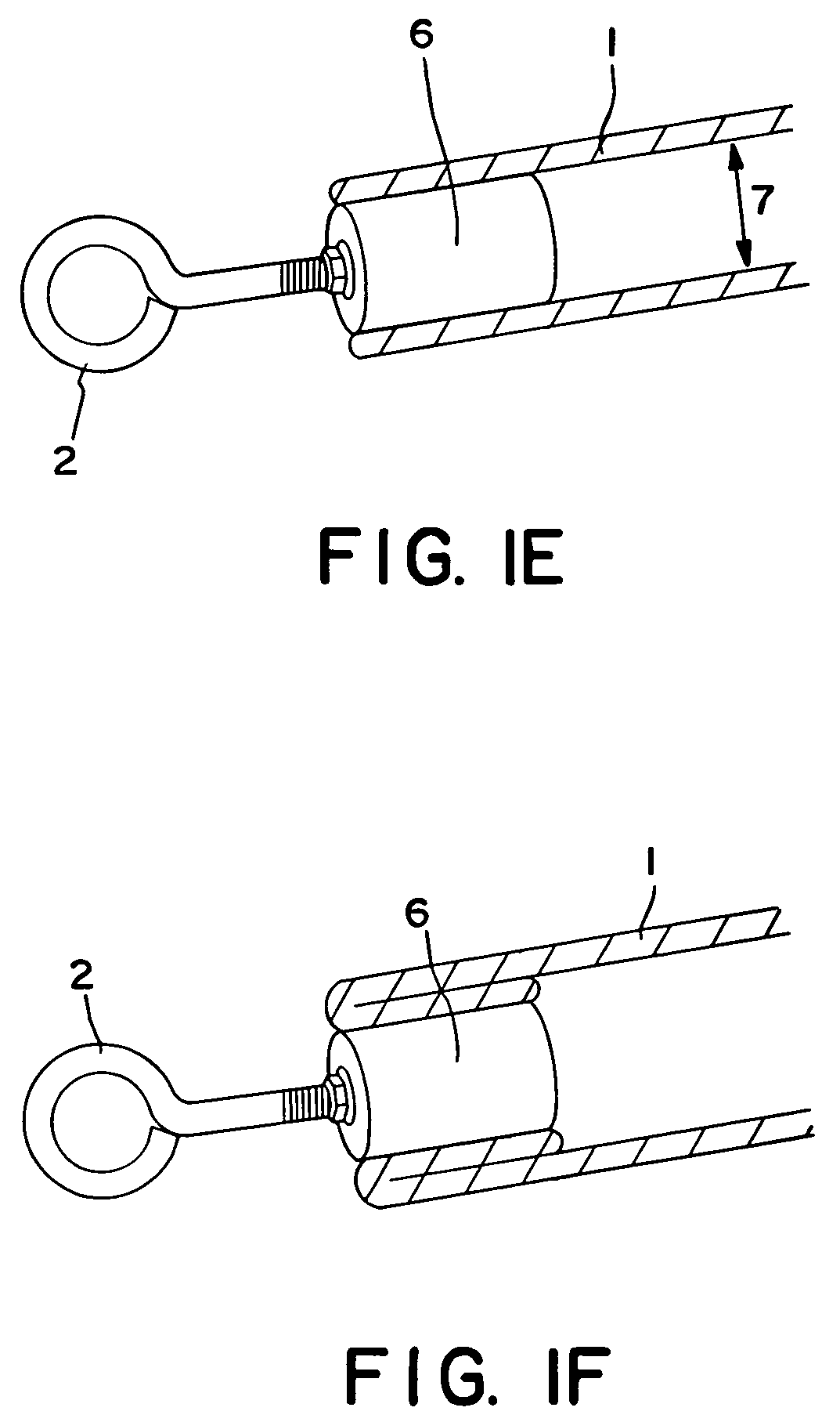
[0033]FIG. 1A shows a connector portion of an exercise system in accordance with the present invention. Illustrated are elastic tubing 1, preferably of pure latex, of ⅛″ wall thickness that provides resistive force to a person using the system, a eye-bolt 2 having a thread portion 4 that is to be threaded through a smaller threaded bushing 6 and a larger threaded bushing 8. With reference to FIG. 4, one or more eye-bolts 2 may be slid onto a hook 10 in order to connect an elastic tube assembly to an engaging member 9 that is intended to engage a portion of the user's body, such as the hands or feet, in order to provide a countering force during the exercise.

[0034]FIG. 1B shows an assembled connector portion, and FIG. 1D illustrates an elastic tube assembly 12 having an eye-bolt disposed at each end. FIG. 1C illustrates a cross section of the assembled co...


PUM


Abstract

Exercise system comprised of plurality of modular components enabling numerous types of exercises. Resistive force provided by durable elastomeric tubing that is quickly connectable to and disconnectable from more rigid components.

Description

FIELD OF THE INVENTION [0001] The present invention relates generally to physical conditioning and / or rehabilitation devices, and more particularly to devices including elastic and rigid components and exhibiting selectable resistive forces and secure mechanical links between the elastic and rigid components. BACKGROUND OF THE INVENTION [0002] More people engage in exercising as a leisure activity than any other type of activity. Portable exercise devices have become more popular because they are generally inexpensive to manufacture and are readily transportable so that a regular program of physical fitness can be maintained. [0003] One simple portable exercise device consists of a bar with a single elastic member three or four feet long and extending between the two ends so that a person could hold the bar and push down on the rope with his feet. A variation of this device consists of an elastic rope with two handles at the ends of the rope replacing the bar. [0004] The resistance ...

Claims


Application Information

Patent Timeline
IPC IPC(8): A63B21/02A63B21/04A63B21/055A63B23/12
CPCA63B21/0004A63B21/00061A63B21/00065A63B21/00069A63B21/04A63B2208/0204A63B21/0552A63B21/0555A63B21/0557A63B21/143A63B23/12A63B21/0442A63B23/03525A63B23/03541A63B23/1209A63B21/4015A63B21/4035A63B21/4043
Inventor DOVNER, EDWARD R.HARVEY, WILLIAM
Owner DOVNER EDWARD R
Why Eureka
Try Eureka