Office chair caster

Inactive Publication Date: 2005-06-02
TSAI PO CHUAN
View PDF10 Cites 20 Cited by
  • Summary
  • Abstract
  • Description
  • Claims
  • Application Information

AI Technical Summary

Benefits of technology

[0005] The main purpose of the invention is to offer an office chair caster being co

Problems solved by technology

However, such an office chair caster 1 designed to have the spindle 11 screwed to the wheel holder 10 by the nut 12 may become unst

Method used


Image

  • Office chair caster
  • Office chair caster
  • Office chair caster

Examples


Embodiment Construction

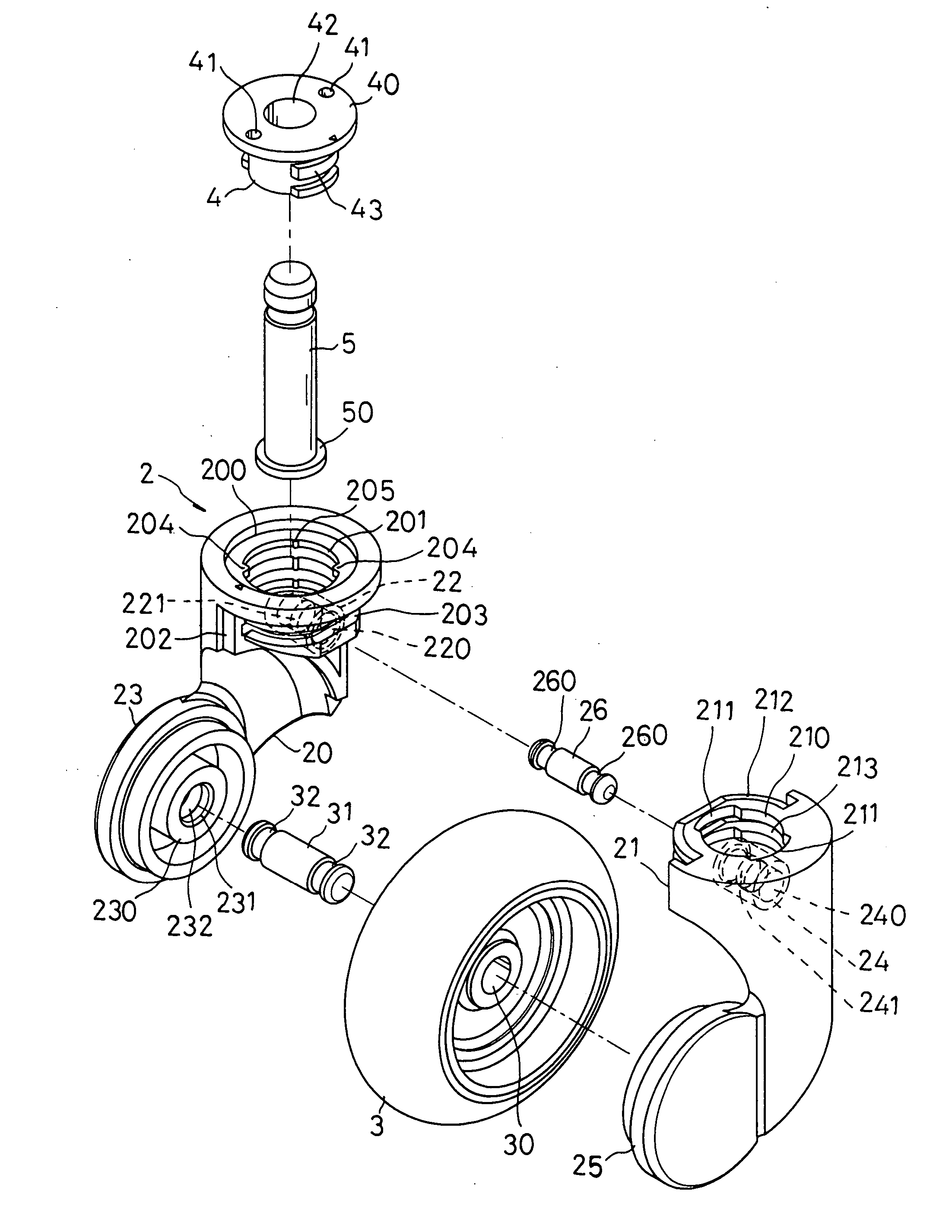
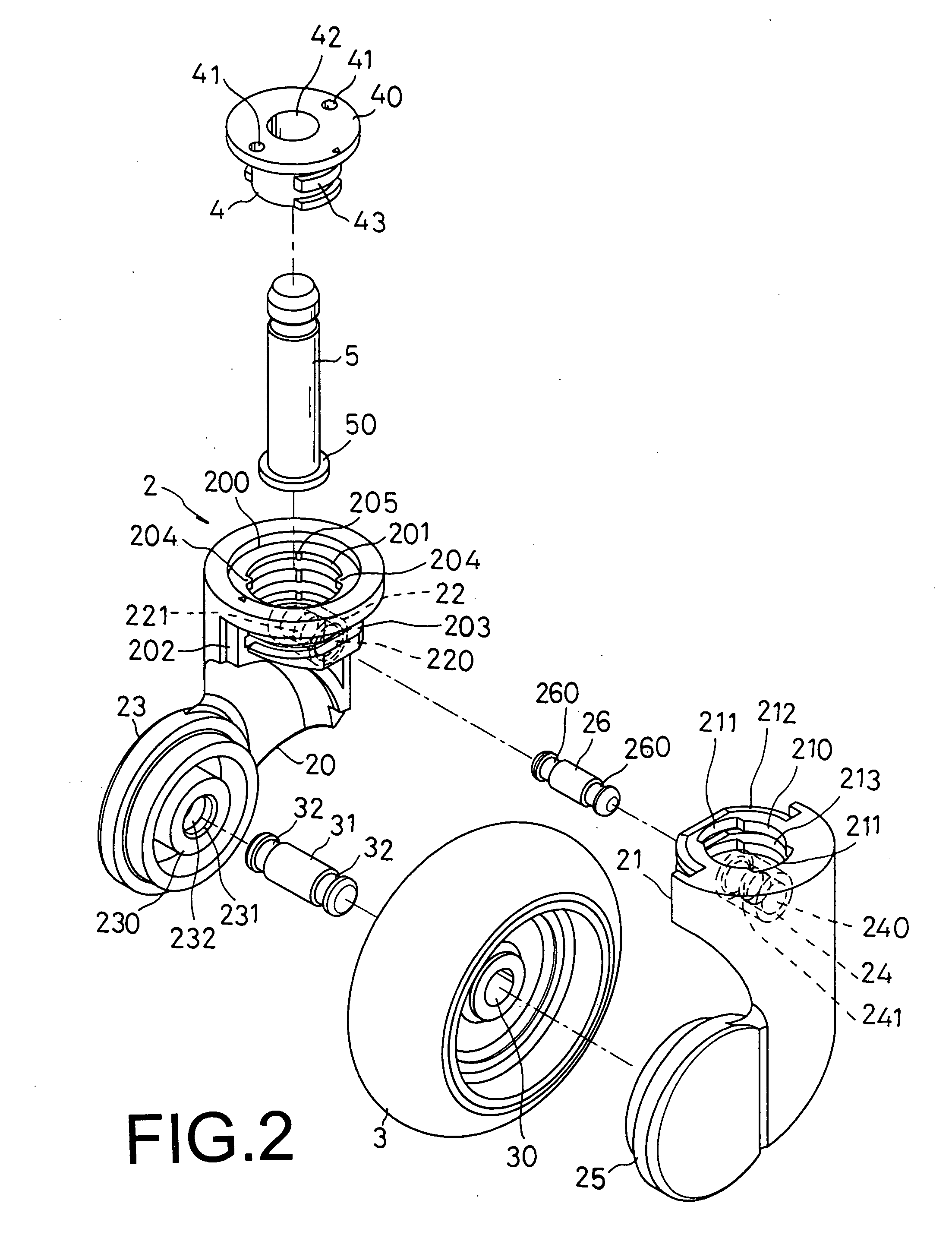
[0022] A preferred embodiment of an office chair caster in the present invention, as shown in FIGS. 2, 3 and 4, mainly includes a wheel holder 2, a wheel body 3, a spindle seat 4 and a spindle 5.

[0023] The wheel holder 2 has a first base 20 and a second base 21 oppositely joined together.

[0024] The first base 20 has a recess 200 disposed thereon, an opening 202 disposed at one side thereof, a rod housing 22 disposed in an interior thereof and a cover plate 23 integrally disposed at a lower portion thereof. The recess 200 is provided with a through hole 201 disposed therein. The through hole 201 is provided with a plurality of fitting slots 203 disposed on a wall thereof and extending therethrough in communication with the opening 202. The through hole 201 is also provided with a plurality of stop blocks 204 oppositely disposed on an inner wall surface thereof and a plurality of projections 205 oppositely disposed on the inner wall surface thereof. The rod housing 22 has a rod hole...


PUM


Abstract

An office chair caster has a wheel holder, a wheel body, a spindle seat and a spindle. Make a first base and a second base oppositely joined together to form the wheel holder with retaining pieces of the second base inserted into fitting slots of the first base, and make the spindle seat that is extended through by the spindle inserted into through holes of the first and second bases with engagement protuberances of the spindle seat aligned with engagement grooves of the second base. The spindle seat can be rotated at 90 degree to make the engagement protuberances impelled over projections of the first base, stopped by stop blocks of the first base, engaged in sliding slots of the second base, and limited between the projections and the stop blocks without moving, thereby the spindle seat can be firmly fixed in the wheel holder to hold the spindle securely.

Description

BACKGROUND OF THE INVENTION [0001] 1. Field of the Invention [0002] This invention relates to an office chair caster, particularly to one capable of firstly having a first base and a second base oppositely joined together to form a wheel holder with a plurality of retaining pieces of the second base inserted into a plurality of fitting slots of the first base, further having a spindle extending through a spindle bore of a spindle seat, and then having the spindle seat inserted into through holes of the first base and the second base with a plurality of engagement protuberances of the spindle seat aligned with a plurality of engagement grooves of the second base, by which the spindle seat can be rotated at 90 degree to make the engagement protuberances of the spindle seat impelled over a plurality of projections that are disposed in an inner wall surface of the through hole of the first base, stopped by a plurality of stop blocks that are also disposed in the inner wall surface of th...

Claims


Application Information

Patent Timeline
IPC IPC(8): A47C7/00B60B33/00
CPCA47C7/006B60B33/0002B60B33/001B60B33/0021B60B33/0028Y10T16/203B60B33/0049B60B33/0057B60B33/0068B60B33/0073B60B33/0039
Inventor TSAI, PO-CHUAN
Owner TSAI PO CHUAN
Why Eureka
Try Eureka