Fuel level sensor

a fuel level sensor and sensor technology, applied in liquid/fluent solid measurement, instruments, machines/engines, etc., can solve the problems of limiting the range of motion of the float, inaccuracy in measuring the level of fuel in the tank, and malfunctions of the mechanical float and wiper assembly

Inactive Publication Date: 2005-06-02
CONTINENTAL AUTOMOTIVE SYST INC
View PDF7 Cites 29 Cited by
  • Summary
  • Abstract
  • Description
  • Claims
  • Application Information

AI Technical Summary

Problems solved by technology

Unfortunately, the harsh petrochemical environment of the fuel tank may lead to malfunctions in the mechanical float and wiper assembly.
Moreover, the mechanical nature of the float mechanism may also lead to inaccuracies in measuring the level of fuel in the tank.
For example, the connection between the wiper and the variable resistor and / or or the top of the tank itself may limit the range of motion of the float.
In a similar manner, inaccuracies may develop when the fuel level approaches the bottom of the tank.
Furthermore, automobile design and construction have become increasingly complex.
Traditional sending units (i.e., those with float assemblies) may be unable to compensate for such contoured designs.

Method used


Image

  • Fuel level sensor
  • Fuel level sensor
  • Fuel level sensor

Examples


Embodiment Construction

[0013] One or more specific embodiments of the present invention will be described below. In an effort to provide a concise description of these embodiments, not all features of an actual implementation are described in the specification. It should be appreciated that in the development of any such actual implementation, as in any engineering or design project, numerous implementation-specific decisions must be made to achieve the developers' specific goals, such as compliance with system-related and business-related constraints, which may vary from one implementation to another. Moreover, it should be appreciated that such a development effort might be complex and time consuming, but would nevertheless be a routine undertaking of design, fabrication, and manufacture for those of ordinary skill having the benefit of this disclosure.

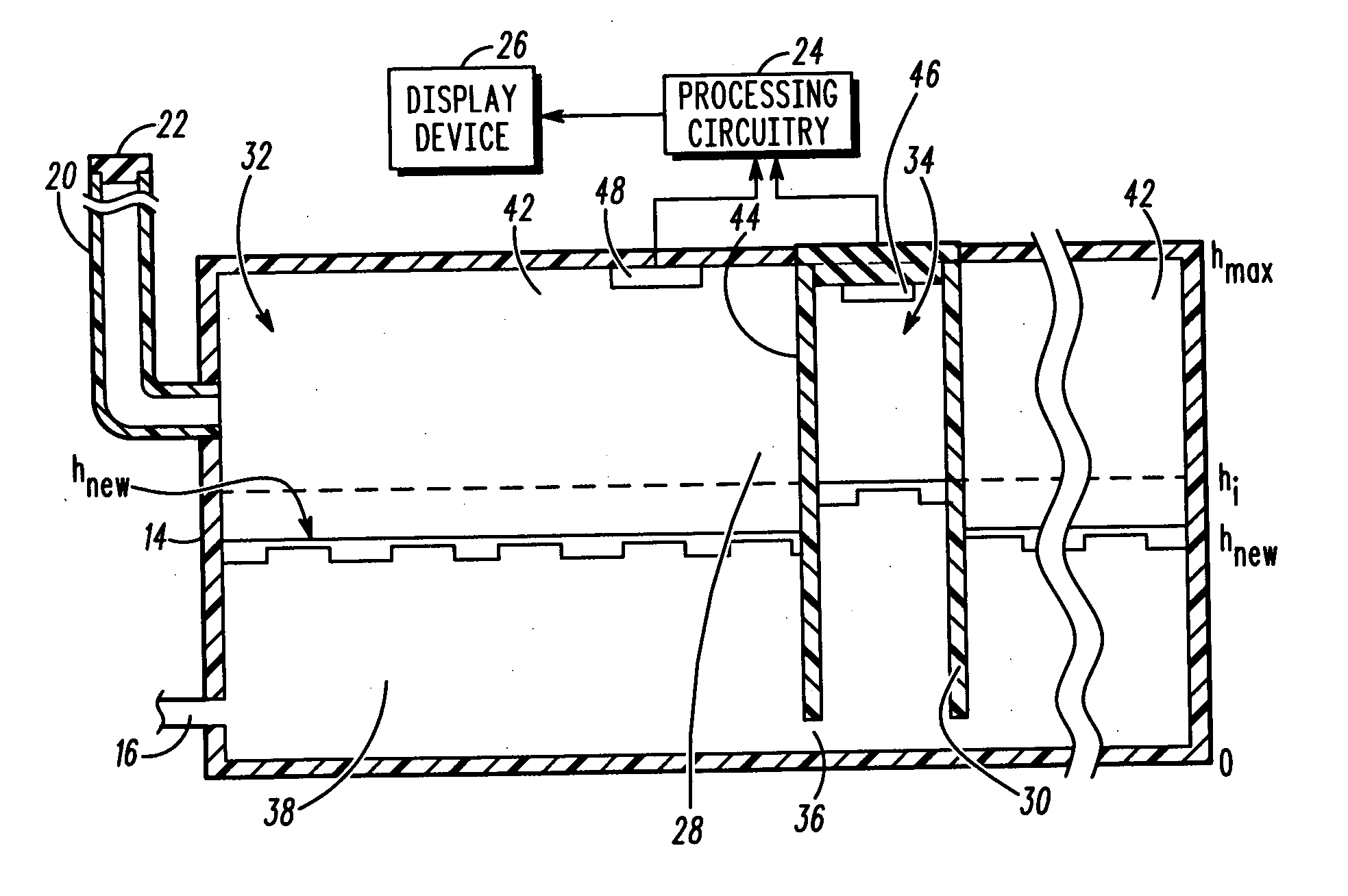
[0014] According to one embodiment of the present technique, our exemplary fuel sensor system is described herein. The fuel sensor system determines pre...


PUM


Abstract

According to an exemplary embodiment, the present technique relates to a fuel sensor for determining operational fuel level (hnew) in a fuel tank (14). In the exemplary embodiment, an isolated airspace (44) is created. By monitoring the pressure conditions in the isolated airspace 44 as well as the pressure and temperature conditions in the remainder (42) of the tank (14), the operational fuel level (hnew) may be determined.

Description

FIELD OF THE INVENTION [0001] The present technique relates to methods and apparatus for determining fuel quantities in fuel tanks. More particularly, the present technique relates to determining fuel quantities by monitoring pressure and temperature conditions of the fuel tank. BACKGROUND INFORMATION [0002] This section is intended to introduce the reader to various aspects of the art that may be related to various aspects of the present invention, which are described and / or claimed below. This discussion is believed to be helpful in providing the reader with background information to facilitate a better understanding of the various aspects of the present invention. Accordingly, it should be understood that these statements are to be read in this light, and not as admissions of prior art. [0003] Internal combustion engines are usually powered by a liquid fuel, which is stored in a tank discrete from the engine. Fuel tanks are generally sized to provide for sustained operation of th...

Claims


Application Information

Patent Timeline
Patent Type & Authority Applications(United States)
IPC IPC(8): G01F23/14G01F23/18
CPCG01F23/18G01F23/14
Inventor MEAGHER, JOHN T.
Owner CONTINENTAL AUTOMOTIVE SYST INC
Why Eureka
Try Eureka