Mobile joint with several stable positions, suitable for use in furniture

a mobile joint and stable position technology, applied in the field of mobile joints with several stable positions, can solve the problems of user's way of use, more susceptible to wear and breakage, and the difficulty of finding or reaching the handl

Inactive Publication Date: 2005-06-02
VARIER FURNITURE AS
View PDF23 Cites 10 Cited by
  • Summary
  • Abstract
  • Description
  • Claims
  • Application Information

AI Technical Summary

Problems solved by technology

However, these chairs usually only have two extreme stable positions, such as a sitting position and a relaxing position.
Such handles are usually difficult to find or reach, as they should preferably not be conspicuous in relation to the appearance of the chair.
When such handles are more accessible, they easily get in the way of the user and are more subject to wear and breakage.
A disadvantage of these chairs is that fo

Method used


Image

  • Mobile joint with several stable positions, suitable for use in furniture
  • Mobile joint with several stable positions, suitable for use in furniture
  • Mobile joint with several stable positions, suitable for use in furniture

Examples


example a

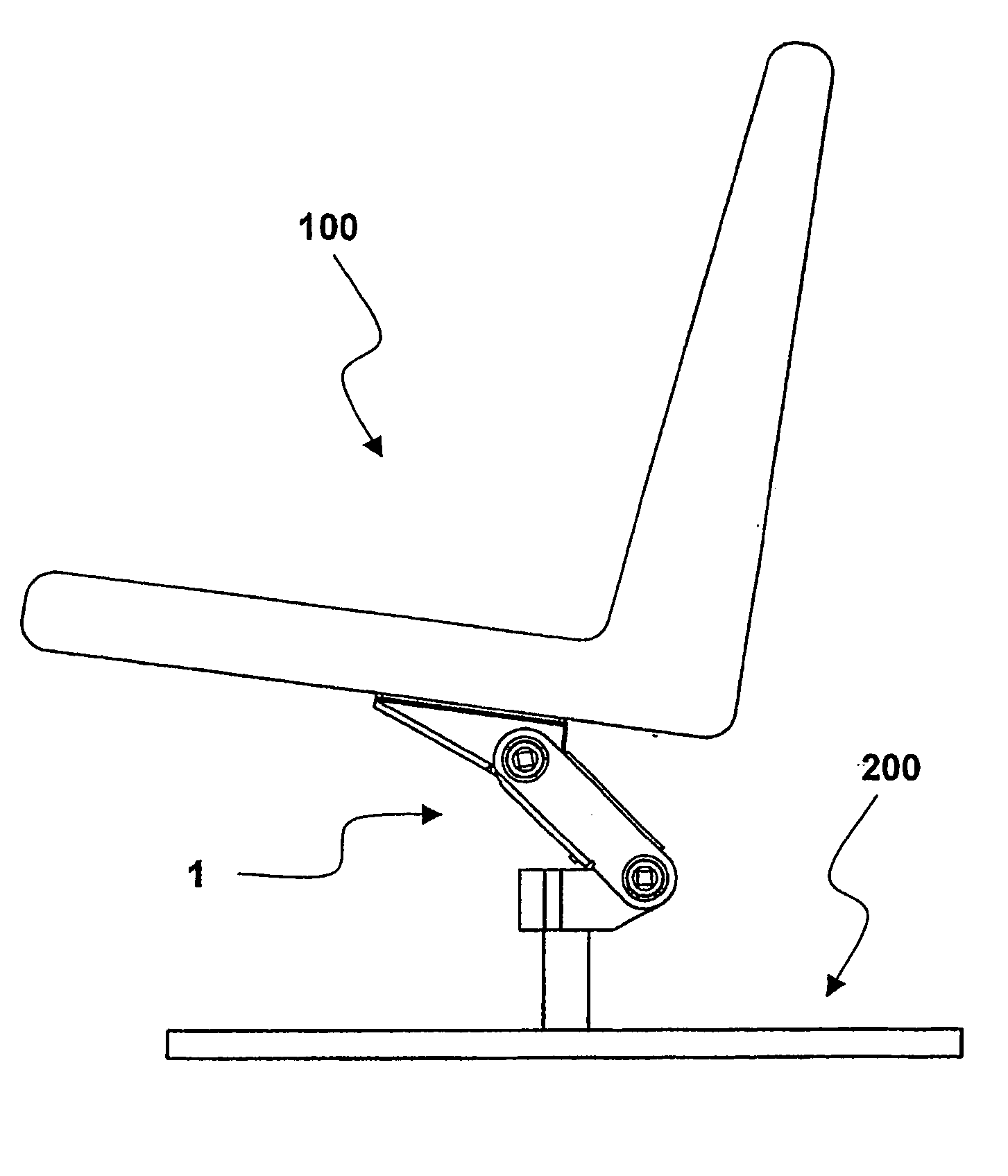
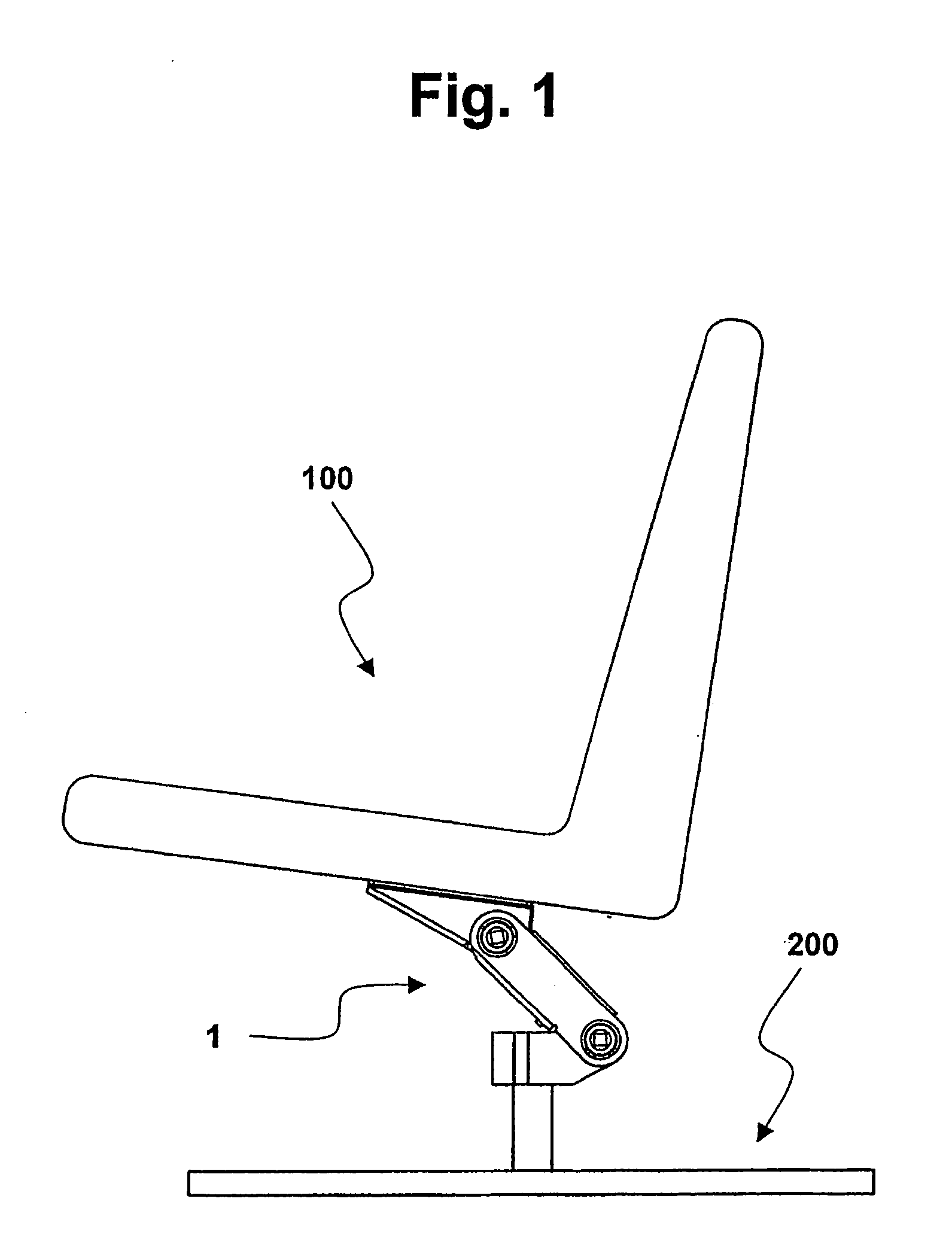
[0025] As shown in FIG. 1, the joint 1 according to the invention is suited as a binding joint between chair seat 100 and a base 200. The base 200 often consists of a vertical base rod, which may perhaps be pivoted / rotational, and a mainly horizontal base foot with a dimension that should prevent the chair from tipping over when the base is not fixed to the support.

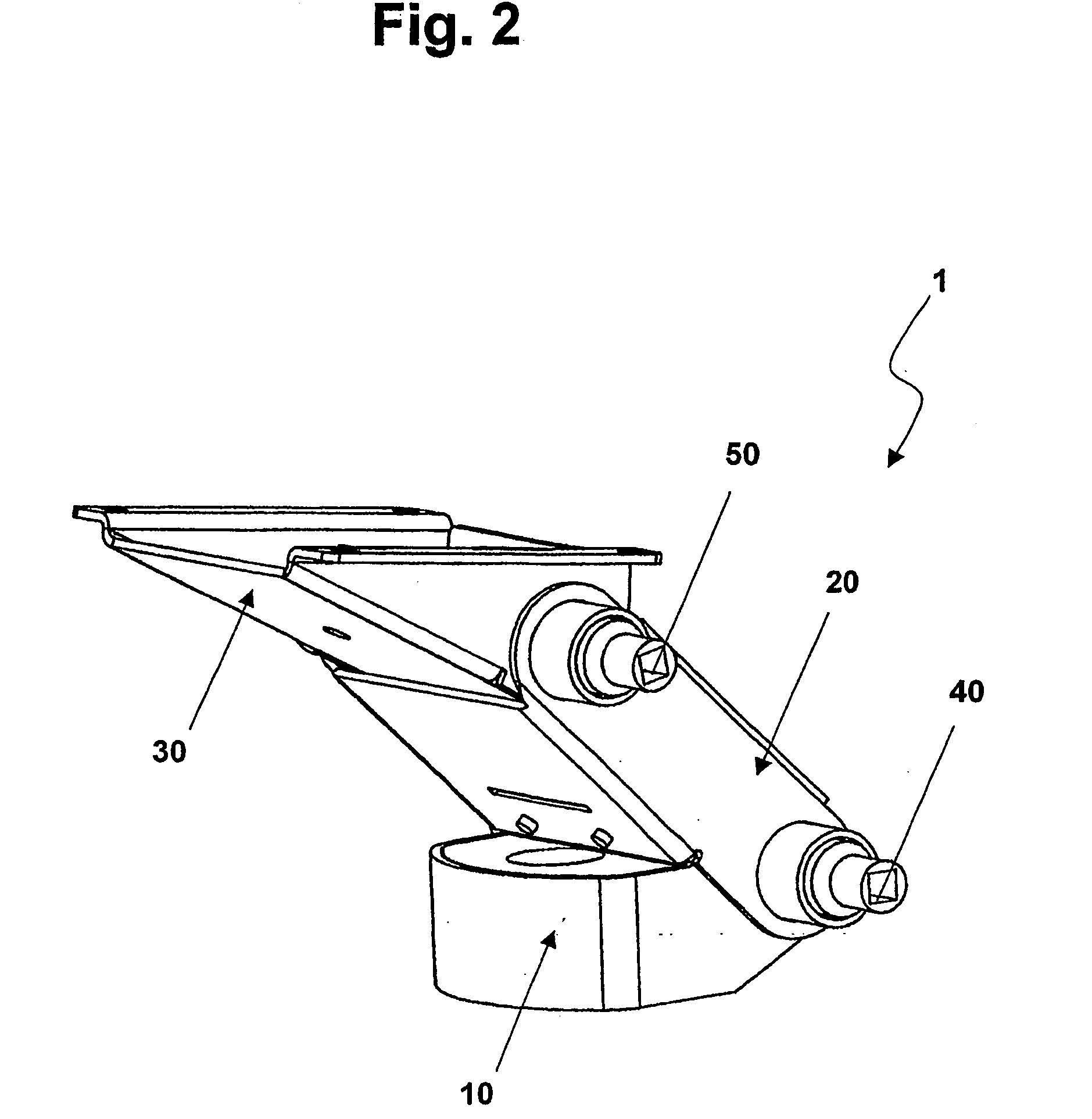
[0026] In this embodiment the joint 1 is assembled as shown in FIG. 2, namely by three joint elements 10, 20 and 30 which are joined by pivoted axles 40 and 50. Each joint element may be pivoted between two extreme positions in relation to each joint element that it is connected to.

[0027] When the joint 1 constitutes a joint between a seat of a chair 100 and a base 200 as in FIG. 1, or another solid element, the joint elements will be designated as “lower joint element”10, “middle joint element”20 and “upper joint element”30.

[0028] In this embodiment the lower joint element 10 is principally parallel to the support and...

example b

[0044]FIG. 9 shows an alternative embodiment of a joint 2 according to the invention as a connecting joint between a chair seat 100 and a base 200. The joint 2 functions according to the same principles as the joint 1 described above, but the joint elements will move in different sequence than in the joint 1 described earlier.

[0045] As may be seen from FIGS. 9 and 10, the joint 2 has a Z-form making it very compact in that the joint elements 10, 20, and 30 lie mainly directly above each other in the vertical direction. Thus, this joint 2 has a narrower tilt-range in the horizontal plane when mounted on a revolving base, than the aforementioned joint 1.

[0046] In FIG. 11, the joint 2 is in an initial position corresponding to the joint 1 in FIGS. 3 and 6. The joint 2 then has an angle α, for example about 8°. In this embodiment, the middle joint element 20 is restricted from further movement forward in that its protruding blocking element 11, lower fitting surface 14, which abuts ag...


PUM


Abstract

The present invention relates to a mobile joint (1) for a seating construction, especially a chair, for mounting between a seat device and a base, comprising at least two joint elements (10, 30) which are reciprocally restricted pivoted between two extreme positions to allow tilting movement of the seating construction effected by the users weight displacement, comprising two outer joint elements (10, 30) which are pivoted related with a middle joint element (20), wherein the rotational axis (40, 50) between the two joint elements (10, 30) and the middle joint element (20) is displaced in relation to each other in the horizontal direction, whereby the joint (1) may assume a stable tilting position between the two extreme positions.

Description

BACKGROUND OF THE INVENTION [0001] The present invention relates to a mobile joint with several stable positions suitable for use in furniture such as a chair, and especially a reclining chair. PRIOR ART [0002] Several types of mobile joints between the seat and base of chairs are known from prior art, especially in office chairs. However, these chairs usually only have two extreme stable positions, such as a sitting position and a relaxing position. In order to use these chairs between the extreme positions, the joint must usually be locked, typically by means of a handle or similar device. Such handles are usually difficult to find or reach, as they should preferably not be conspicuous in relation to the appearance of the chair. When such handles are more accessible, they easily get in the way of the user and are more subject to wear and breakage. [0003] Further, there exist several different recliners with reclining backrest. In these chairs, the chair back may often be reclined ...

Claims


Application Information

Patent Timeline
IPC IPC(8): A47C3/026A47C1/032
CPCA47C3/026A47C7/448A47C7/445
Inventor WULLUM, OLE PETTER
Owner VARIER FURNITURE AS
Why Eureka
Try Eureka