Al technical title is built by PatSnap Al team. It summarizes the technical point description of the patent document.
a shoulder and joint surgery technology, applied in the field of shoulder surgery, can solve the problems of shoulder joint pain, surgical procedure can become quite physically taxing on the surgeon or surgeon, and contribute to surgical errors
Inactive Publication Date: 2005-06-02
MINNESOTA SCI
View PDF23 Cites 243 Cited by
Summary
Abstract
Description
Claims
Application Information
AI Technical Summary
This helps you quickly interpret patents by identifying the three key elements:
Problems solved by technology
Method used
Benefits of technology
[0010] The present invention includes a method of performing a shoulder joint surgery involving a scapula having a glenoid cavity, a humerus and a humeral ball on a surgical table. The method includes mounting a retractor support to the surgical table and positioning the retractor
Problems solved by technology
The deterioration causes either the humeral ball, the glenoid cavity or both the humeral ball and the glenoid cavity become rough which results in pain when the shoulder joint is articulated.
Due to the multiple dislocations and insertions of the humeral ball into the glenoid cavity, as well as retracting the humerus, the surgical procedure can become quite physically taxing on the surgeon or surgeons.
Depending on the size of the p
Method used
Image
Click on the blue label to locate the original text in one second.
Reading with bidirectional positioning of images and text.
Examples
Embodiment Construction
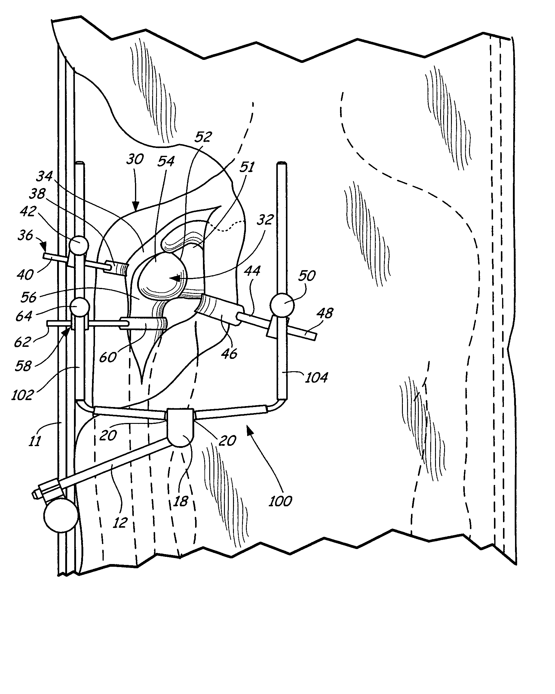
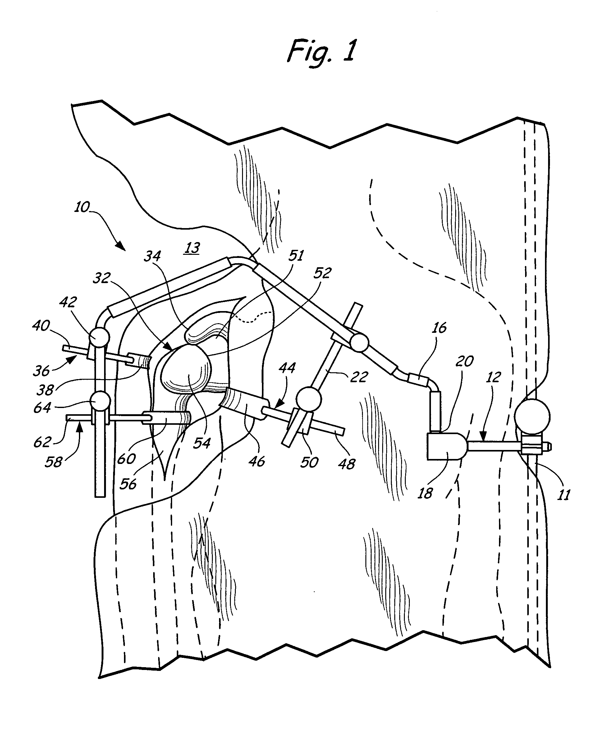
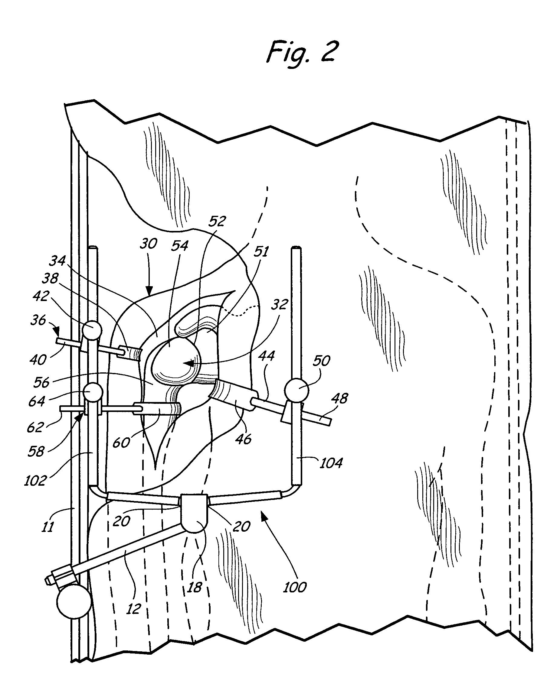
[0015] The present invention relates to a method of performing surgical procedures on a shoulder joint. An apparatus used in the surgical procedures of the present invention is generally indicated at 10 in FIG. 1.
[0016] The apparatus 10 includes a retractor support apparatus 12 that is rigidly mounted to a rail 11 of a surgical table 13 in a manner that is well known in the art and is described in U.S. Pat. Nos. 4,617,916, 4,718,151, 4,949,707, 5,400,772, 5,741,210, 6,042,541, 6,264,396 and 6,315,718 all of which are herein incorporated by reference. From the mount to the surgical table 13, the retractor support apparatus 12 includes at least one support arm that extends over the surgical table 13. The support arm 16 is removably attached to a clamping mechanism 18 having at least one pivot ball 20 rotatably movable within a clamping bore (not shown). The pivot ball 20 includes a cavity (not shown) into which an end of the support arm 16 is inserted. The support arm 16 is adjustabl...
PUM
Abstract
A method of performing a shoulder joint surgery involving a scapula having a glenoid cavity, a humerus and a humeral ball on a surgical table includes mounting a retractor support to the surgical table and positioning the retractor support about the shoulder joint. The skin and flesh layers proximate the shoulder joint are incised and the skin and flesh layers are manually retracted with a retractor. The retractor is secured in a selected position by attaching the retractor to the retractor support.
Description
CROSS REFERENCE TO RELATED APPLICATIONS [0001] This application is a continuation-in-part of application Ser. No. 10 / 728,202 filed on Dec. 4, 2003, which is hereby incorporated by reference in its entirety, which is a continuation of application Ser. No. 10 / 077,693, filed Feb. 15, 2002, which is incorporated by reference in its entirety, and resulting in U.S. Pat. No. 6,659,944, which is a continuation of application Ser. No. 09 / 990,420 filed on Nov. 21, 2001, which is incorporated by reference in its entirety, and resulting in U.S. Pat. No. 6,368,271. [0002] This application is also a continuation-in-part of application Ser. No. 10 / 892,816 filed on Jul. 16, 2004, which is hereby incorporated by reference in its entirety, which is a continuation-in-part of application Ser. No. 10 / 623,179; filed Jul. 18, 2003, which is hereby incorporated by reference in its entirety, which claims priority of U.S. Provisional Application No. 60 / 396,850, filed Jul. 18, 2002, the content of which is he...
Claims
Application Information
Patent Timeline
Application Date:The date an application was filed.
Publication Date:The date a patent or application was officially published.
First Publication Date:The earliest publication date of a patent with the same application number.
Issue Date:Publication date of the patent grant document.
PCT Entry Date:The Entry date of PCT National Phase.
Estimated Expiry Date:The statutory expiry date of a patent right according to the Patent Law, and it is the longest term of protection that the patent right can achieve without the termination of the patent right due to other reasons(Term extension factor has been taken into account ).
Invalid Date:Actual expiry date is based on effective date or publication date of legal transaction data of invalid patent.