
Selectively passive forward shielding medical needle device

a forward shielding and needle device technology, applied in the field of medical devices, can solve the problems of undesirable partial or full retraction awkward release of the latching mechanism, and inability to maintain control of the needle cannula

Inactive Publication Date: 2005-06-02
BECTON DICKINSON & CO
View PDF18 Cites 87 Cited by
  • Summary
  • Abstract
  • Description
  • Claims
  • Application Information

AI Technical Summary

Benefits of technology

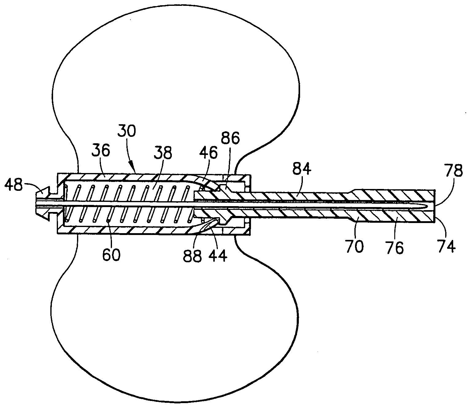
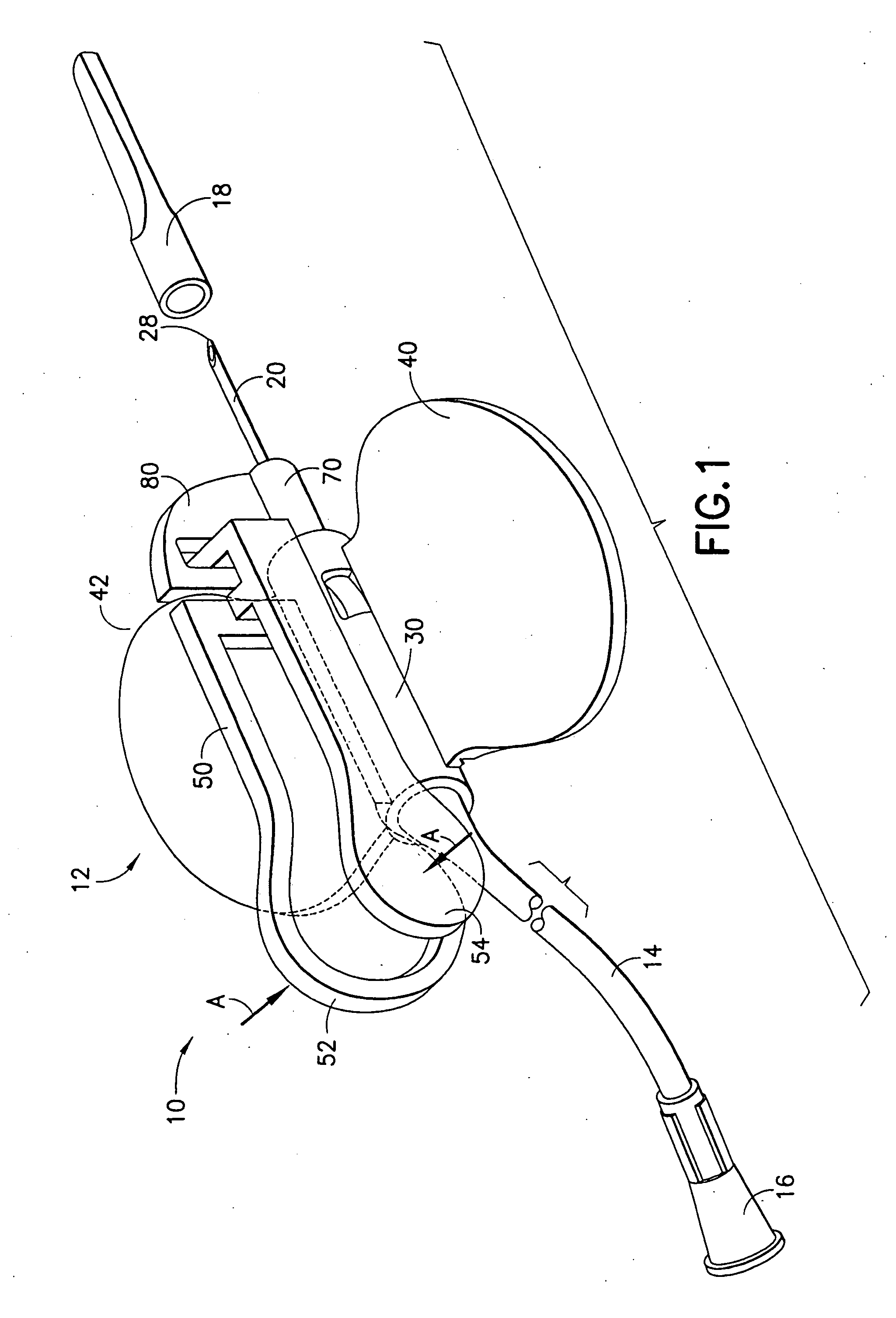
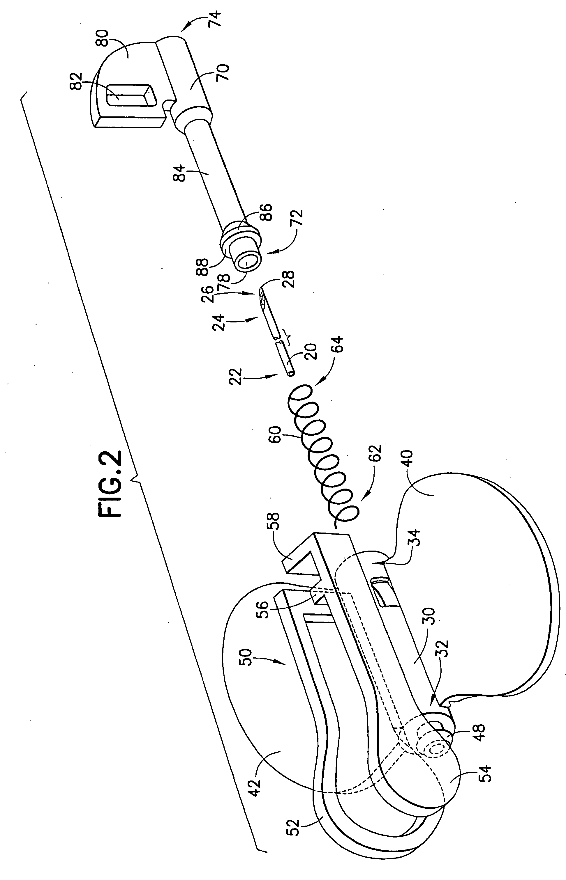
[0009] The present invention relates generally to a safety needle system in the form of a shielding medical needle device for shielding used needle cannulas. The shielding medical needle device generally includes a hub housing and an elongated shield housing. A needle cannula having a distal puncture tip extends from the hub housing, with at least a portion of the needle cannula extending through the passageway of the shield housing. A biasing member such as a compression spring acts on the shield housing to bias the shield housing from a first biased position adjacent the hub housing toward a second position covering the distal puncture tip of the needle cannula. An engagement mechanism extends dorsally from the hub housing and is in releasable engagement with a portion of the shield housing for releasably retaining the shield housing in the first biased position adjacent the hub housing. Activation of the engagement mechanism releases the engagement mechanism from engagement with the shield housing. As such, the shield housing is released from the biased position, with the biasing member causing the shield housing to move toward the second position. Since the engagement mechanism extends dorsally from the device, activation of the device to shield the needle can be effectively accomplished during removal of the needle device from a patient, thereby providing for a passive activation of the device during normal use.
[0013] In a further embodiment, the present invention is directed to a method for passively activating a safety needle system. The method includes providing a safety needle system comprising a hub housing including a needle cannula extending from a distal end of the hub housing toward a distal puncture tip; a shield housing covering at least a portion of the needle cannula adjacent the hub housing; a biasing element for biasing the shield housing toward a shielding position fully covering the distal puncture tip of the needle cannula; and a latch mechanism extending dorsally from the safety needle system for maintaining the shield housing in a biased state adjacent the hub housing. The method further includes inserting the safety needle system into a patient, and withdrawing the safety needle system from the patient by grasping the latch mechanism, thereby releasing the shield housing from the biased state and causing the shield housing to extend toward the shielding position. Desirably, the hub housing further includes a pair of flexible wings extending from opposing lateral sides thereof. In such an arrangement, the inserting step may include bending the flexible wings to a dorsal position for guiding the needle cannula into the patient. Such bending of the flexible wings to a dorsal position does not cause the latch mechanism to release the shield housing from the biased state. Further, the shield housing may be prevented from re-exposing the distal puncture tip of the needle cannula once the shield housing has been extended to a fully shielding position, such as through a locking mechanism.
[0014] In yet a further embodiment, the present invention is directed to a safety needle system which includes a grippable dorsal housing having distal and proximal dorsal housing portions. The proximal dorsal housing portion supports a needle, and the distal dorsal housing portion extends in an axial direction with respect to the needle from a first position adjacent the proximal housing portion to a second position covering a distal tip of the needle. A planar wing structure is integral to at least one of the proximal and / or distal dorsal housing portions, and extends in a direction which is generally normal to the grippable dorsal housing. A biasing element such as a spring extends between the distal and proximal dorsal housing portions for biasing the dorsal housing portion toward the second position. A release element, such as a release latch on the proximal dorsal housing portion in interference engagement with a recess or opening in the distal dorsal housing portion, selectively retains the distal dorsal housing portion in the first position adjacent the first housing portion against the bias of the biasing element. Activation of the release element causes the biasing element to act on the distal dorsal housing portion to move the distal dorsal housing portion to the second position.

Problems solved by technology

Release of the latching mechanism is awkward due to the relation between the latching mechanism extending between the shield portion and the hub.
Further, this device requires the operator to exert a substantial force to shield the needle cannula, and is prone to rotation of the needle cannula within the shield portion during the shielding operation.
However, since retraction of such a device is achieved by holding the safety shield, the user does not hold the needle cannula during retraction and therefore does not maintain control over the needle cannula.
Thus, if the latch is released while the needle cannula is inserted in a patient or during withdrawal from the patient, the spring force may cause an undesirable partial or full retraction of the needle cannula, instead of merely passively activating the device to allow for complete retraction upon full removal from the patient.

Method used


Image

  • Selectively passive forward shielding medical needle device
  • Selectively passive forward shielding medical needle device
  • Selectively passive forward shielding medical needle device

Examples


Embodiment Construction

[0029]FIGS. 1-10 generally illustrate a medical device according to the present invention. The medical device of the present invention generally includes a shieldable safety needle system adapted to enclose or surround a used needle cannula at the end of a medical procedure, such as a blood collection procedure. The medical device may be used as part of a fluid collection set used to collect blood or other fluids from the body of a human or animal. While described herein in terms of a blood collection set 10, it is noted that the medical device of the present invention including the safety needle system may be used with any medical device incorporating a needle, such as a syringe system, a double-ended phlebotomy needle, or the like. Preferably, the medical device includes a portion that is automatically biased to a safety, needle-enclosing position during normal use by a user of the medical device resulting in a passive activation of the safety features of the assembly, as discusse...


PUM


Abstract

A shieldable needle device for shielding used needle cannulas. The device generally includes a hub housing and an elongated shield housing. A needle cannula having a distal puncture tip extends from the hub housing, with at least a portion of the needle cannula extending through the passageway of the shield housing. A biasing member acts on the shield housing to bias the shield housing from a first biased position adjacent the hub housing toward a second position covering the distal puncture tip of the needle cannula. An engagement mechanism extends dorsally from the hub housing and is in releasable engagement with a portion of the shield housing for releasably retaining the shield housing in the first biased position adjacent the hub housing. Activation of the engagement mechanism to shield the needle can be effectively accomplished during removal of the needle device from a patient, thereby providing for a passive activation of the device during normal use.

Description

BACKGROUND OF THE INVENTION [0001] 1. Field of the Invention [0002] The present invention relates to a medical device for safe and convenient handling of used needle cannulas. More particularly, the present invention relates to a medical needle device that is adapted to automatically shield a needle cannula during normal use in a medical procedure. [0003] 2. Description of Related Art [0004] Blood collection sets or intravenous (IV) infusion sets typically include a needle cannula having a proximal end, a distal end with a puncture tip, and a lumen extending therebetween. The proximal end of the needle cannula is mounted to a plastic hub having a central passage that communicates with the lumen in the needle cannula. A thin flexible thermoplastic tube is connected to the hub and communicates with the lumen in the needle cannula. The end of the plastic tube remote from the needle cannula may include a fixture for connecting the needle cannula to a separate medical device, such as a h...

Claims


Application Information

Patent Timeline
Patent Type & Authority Applications(United States)
IPC IPC(8): A61M5/32A61M25/06
CPCA61M5/3243A61M5/3257A61M2005/325A61M25/0631A61M25/0637A61M25/0618
Inventor CRAWFORD, JAMIESON
Owner BECTON DICKINSON & CO
Learn More