

Microchip and blood monitoring device
A micro-chip technology, applied in measuring devices, biological testing, transportation and packaging, etc., can solve the problems of blood coagulation, large micro-chips, difficult to observe, etc., to achieve longer residence time, prevent blood coagulation, and inhibit blood coagulation The effect of activation
- Summary
- Abstract
- Description
- Claims
- Application Information
AI Technical Summary
Problems solved by technology
Method used
Image

Examples
Embodiment 1
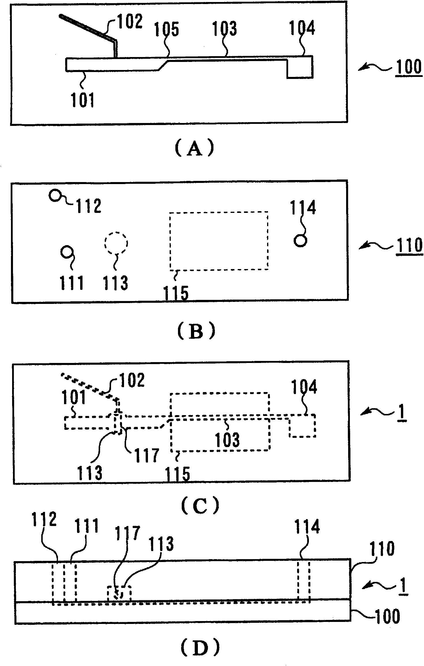
[0225] Fabrication of microflakes and blood observation devices
[0226] prepare as figure 1 The first substrate 100 shown in (A) and the figure 1 The second substrate 110 shown in (B) is two transparent substrates (injection molded products manufactured by Richell Corporation). The flow path opening side of the first substrate 100 is opposed to the opening side of the second substrate 110 which is the hole of the stirring part 113, and they are laminated using an adhesive, as figure 1 (C), figure 1 (D) Microflake 1 shown. Furthermore, the depth of each flow path was 0.12 mm, the width of the first flow path 101 was 1.2 mm, and the width of the constricted part of the joining flow path 103 was 0.3 mm. The stirrer 117 is a cylindrical shape with a diameter of 1 mm and a length of 2 mm formed by covering an iron cylinder with PVLA, and the stirrer 117 is accommodated in the stirring unit 113 . The hole serving as the stirring portion 113 is a through hole having a circula...
Embodiment 2
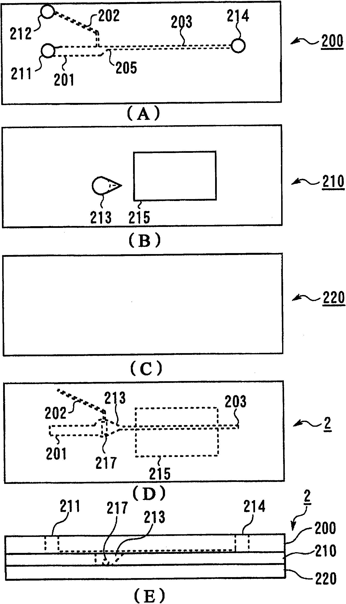
[0233] microflakes
[0234] prepare as figure 2 The first substrate 200 shown in (A) and the figure 2 The second substrate 210 shown in (B) is two transparent substrates (injection molded products manufactured by Fluidware Technologies Inc.) and a transparent acrylic plate such as figure 2 (C) shows the third substrate 220 . The opening surface of the flow path of the first substrate 200 is opposed to the opening surface of the second substrate 210 which is the hole of the stirring part 213, and they are laminated with an adhesive. The opening of the hole of the stirring part 213 of the second substrate 200 is closed by the third substrate 220 using an adhesive, as figure 2 (D) and figure 2 (E) Microflake 2 shown. Furthermore, the thickness of the second substrate 210 is 1.2 mm, which matches the depth of the hole serving as the stirring part 213 . The hole as the stirring part 213 of the second substrate 210 is as follows figure 2 (B) and figure 2 The shape s...
Embodiment 3
[0239] Except that the stirring part 213 of the second substrate 210 in Example 2 is a single circular through hole with an inner diameter of 3 mm, the microchip 2 and the blood observation device were produced in the same manner as in Example 2, and were confirmed in the same manner as in Example 2. Mixed State Experiments. As a result, although the two liquids are uniformly mixed, air remains in the stirring part.
PUM
 Abstract
Description
Claims
Application Information