
Method of co-producing activated carbon in a circulating fluidized bed gasification process

a fluidized bed and gasification process technology, applied in the direction of inorganic chemistry, combustible gas production, chemistry apparatus and processes, etc., can solve the problems of limited removal of pollutants, significant risk to public health, and recent determination of mercury emissions from coal-fired power plants

Inactive Publication Date: 2006-06-22
FOSTER WHEELER ENERGY CORP
View PDF13 Cites 22 Cited by
  • Summary
  • Abstract
  • Description
  • Claims
  • Application Information

AI Technical Summary

Benefits of technology

[0012] An object of the present invention is to provide an efficient method of co-producing activated carbon from a fluidized bed gasification process.
[0013] Another object of the present invention is to enhance the competitiveness of coal gasification by co-producing activated carbon as a valued byproduct.
[0018] In a circulating fluidized bed gasifier, the fuel is circulating for an extended time from the reactor to the particle separator and via the return duct back to the reactor. Thus, the total residence time of the fuel in the fluidized bed and, consequently, the time being affected by the activating agent, is long enough to impart a highly porous structure to the char particles, so as to produce activated carbon in the solids product. A circulating fluidized bed gasifier provides a relatively uniform and controllable temperature, so that the activation process of the char can be optimized to provide a desired pore structure to the produced activated carbon. Also, the activation agent is effectively mixed with the char in the strongly turbulent bed of particles, and causes efficient activation of the char.

Problems solved by technology

Even if the levels of mercury in coals are low, mercury emissions from coal-fired power plants have recently been determined to pose a significant risk to public health.
First, the removal of pollutants is limited by diffusion of the pollutants to the carbon surface during a short contact time (about 1 second) rather than the capacity or activity of the adsorbent.

Method used


Image

  • Method of co-producing activated carbon in a circulating fluidized bed gasification process

Examples


Embodiment Construction

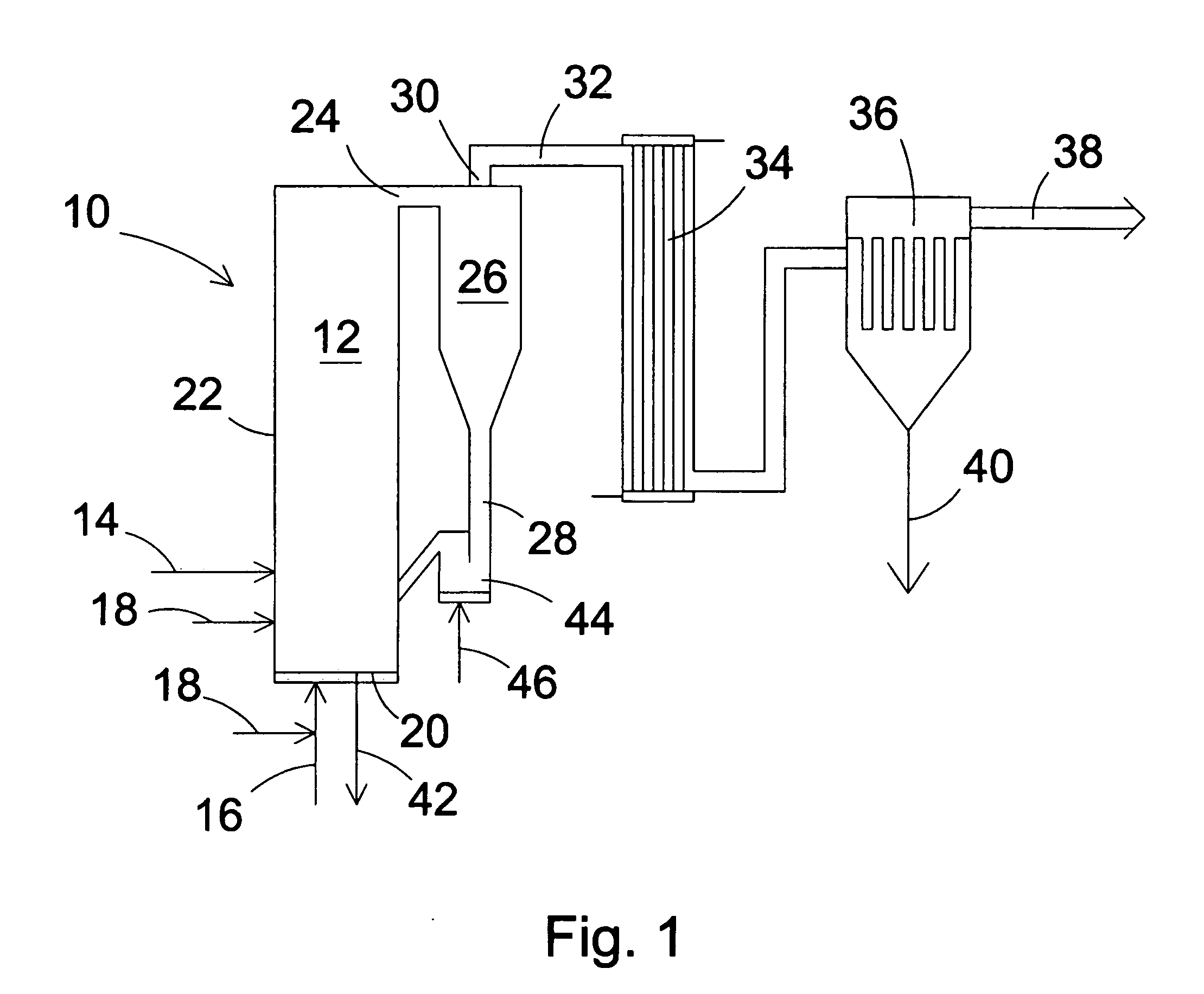
[0023]FIG. 1 schematically illustrates a circulating fluidized bed (CFB) gasifier 10 which can be used in a preferred embodiment of a gasification process in accordance with the present invention. The CFB gasifier 10 comprises a reaction chamber 12 with a fuel supply 14 for feeding carbonaceous fuel to a particle bed formed in the reaction chamber 12. The chamber 12 also comprises an oxidizing gas supply 16 for feeding oxidizing gas (usually air), and an activating agent supply 18 for feeding activation agent, steam, and / or carbon dioxide, at controlled rates into the reaction chamber 12. The activation agent supply 18 may be fed to the reaction chamber 12 through the bottom grid 20, possibly premixed with the oxidizing gas (the lower instance of activation agent supply 18 in FIG. 1), and / or at higher elevations through a side wall 22 of the reaction chamber 12 (the upper instance of activation agent supply 18 in FIG. 1).

[0024] The fuel and other particulate solids in the bed are f...


PUM

PropertyMeasurementUnit
Temperatureaaaaaaaaaa
Timeaaaaaaaaaa
Pressureaaaaaaaaaa

Abstract

A method of co-producing activated carbon in a circulating, fluidized bed gasification process includes gasifying carbonaceous fuel in a fluidized bed to form syngas and char, activating the char to form particles of activated carbon, discharging syngas and particulate solids entrained with the syngas from the reactor, separating entrained solids from the syngas with a particle separator and returning at least a portion of the separated solids to the reaction chamber, but allowing a solids product, including activated carbon and having an average size smaller than a predetermined size, to exit the particle separator with the syngas. The solids product is separated from the syngas in a dust separator to form cleaned syngas, and both the cleaned syngas and the solids product are discharged from the gasifier.

Description

BACKGROUND OF THE INVENTION [0001] 1. Field of the Invention [0002] The present invention relates to a method of co-producing activated carbon in a fluidized bed gasification process, which activated carbon is especially suitable for removing mercury from the flue gases of combustion processes. [0003] 2. Description of Related Art [0004] Activated carbon (AC) is an effective adsorbent primarily due to its extensive porosity and very large available surface area. It is capable of removing low levels of organic and inorganic contaminants or impurities via transfer from the gas or liquid phase of a fluid that is being treated to the solid carbon surface of the AC. Activated carbon has been widely used to treat fluids in a large number of civil and industrial applications, such as water purification, wastewater treatment, sugar refining, beverage filtration, and air pollution control. [0005] One of the applications for AC is mercury capture from the exhaust gases of industrial and combu...

Claims


Application Information

Patent Timeline
IPC IPC(8): C10J3/46
CPCB01J20/20C10J3/56C10J3/78C10J2300/0956C10J2300/0969C10J2300/0973C10J2300/1884C01B32/336Y02C20/40
Inventor GIGLIO, ROBERTFAN, ZHENFROEHLICH, ROBERTROBERTSON, ARCHIBALDSELLAKUMAR, KUMARWU, SONG
Owner FOSTER WHEELER ENERGY CORP
Learn More