
Fastening tool with modified driver travel path

a technology of driver travel path and fastening tool, which is applied in the direction of nailing tools, fastening means, nails, etc., can solve the problems of shortening the drive stroke, affecting the effect of fastening, so as to achieve the effect of limiting the drive stroke length

Inactive Publication Date: 2005-06-09
BOSWINKEL ONNO +1
View PDF26 Cites 0 Cited by
  • Summary
  • Abstract
  • Description
  • Claims
  • Application Information

AI Technical Summary

Benefits of technology

[0010] The problems of the prior art have been overcome by the present invention, which provides a fastening tool for driving a fastener into a substrate wherein the length of the drive stroke of the driver is limited. That is, the path of the drive blade has been modified (relative to conventional staple guns) in order to ensure that the fastener is positioned with respect to the object to be fastened such that desired tension of the fastener on the object to be fastened, the desired holding power of the fastener, and the desired movement of the object to be fastened under the fastener, are achieved.
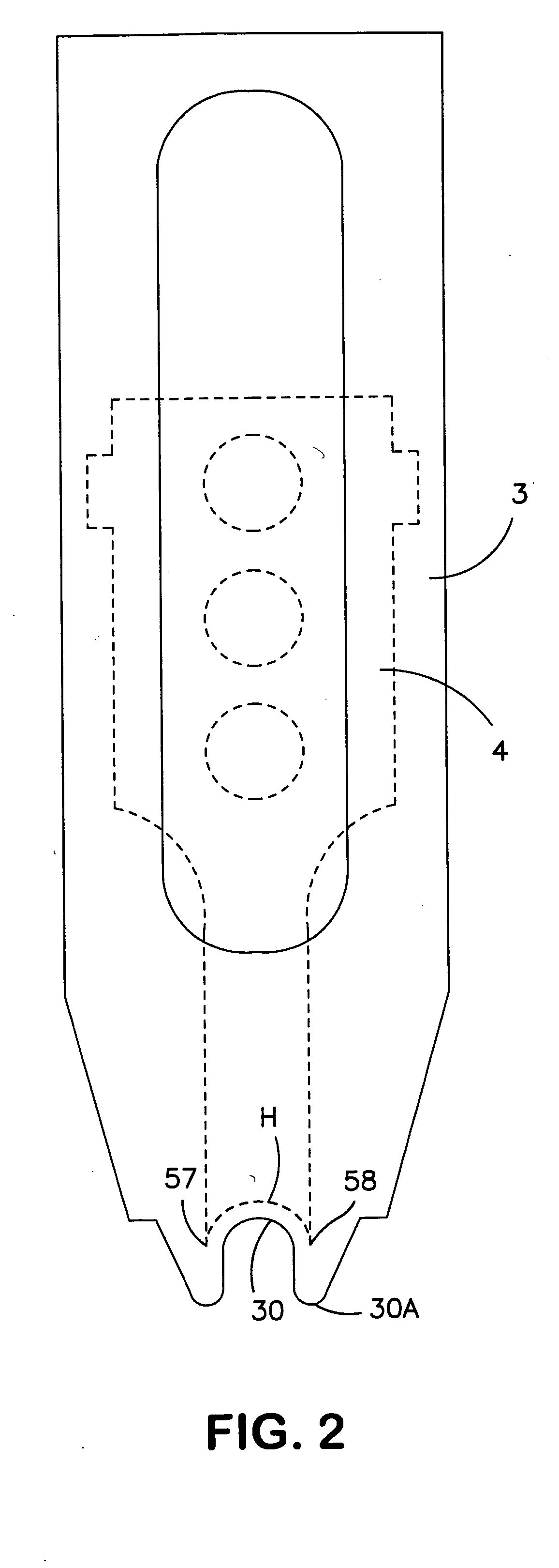
[0012] In one embodiment, the drive stroke of the driver terminates upon contact with an impact pad of appropriate dimension and composition appropriately positioned in the path of the driver so as to effectively limit the length of the drive stroke to achieve the desired fastening.

Problems solved by technology

However, the fastener being applied may at the time of application (due to the impact of the fastener) or subsequently (due to wire and / or substrate expansion or contraction over time) penetrate, damage or deform the item being fastened, resulting in an electrical short circuit, leak or other deleterious effect.
However, this method is slow, tedious, and not very precise.
However, if the fastener is driven too deeply into the substrate, the fastener can deform the wire, cable, tube or other object being fastened.

Method used


Image

  • Fastening tool with modified driver travel path
  • Fastening tool with modified driver travel path
  • Fastening tool with modified driver travel path

Examples


Embodiment Construction

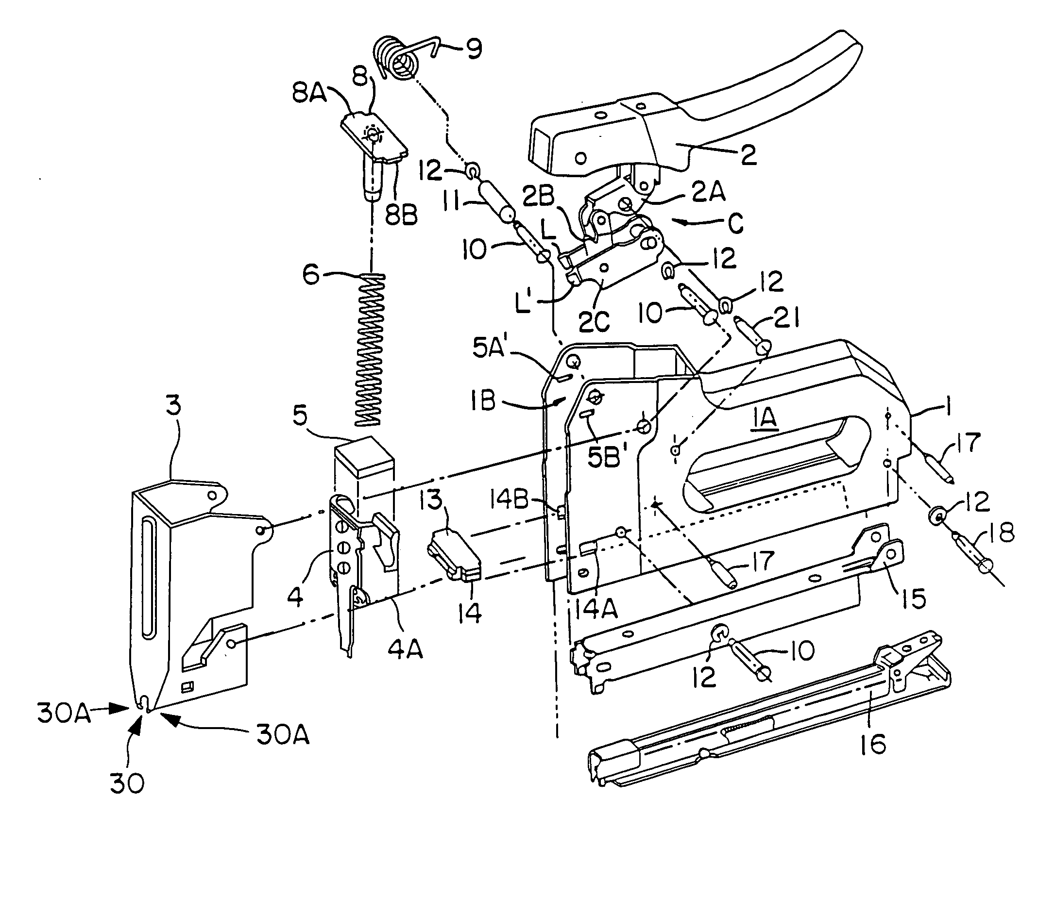
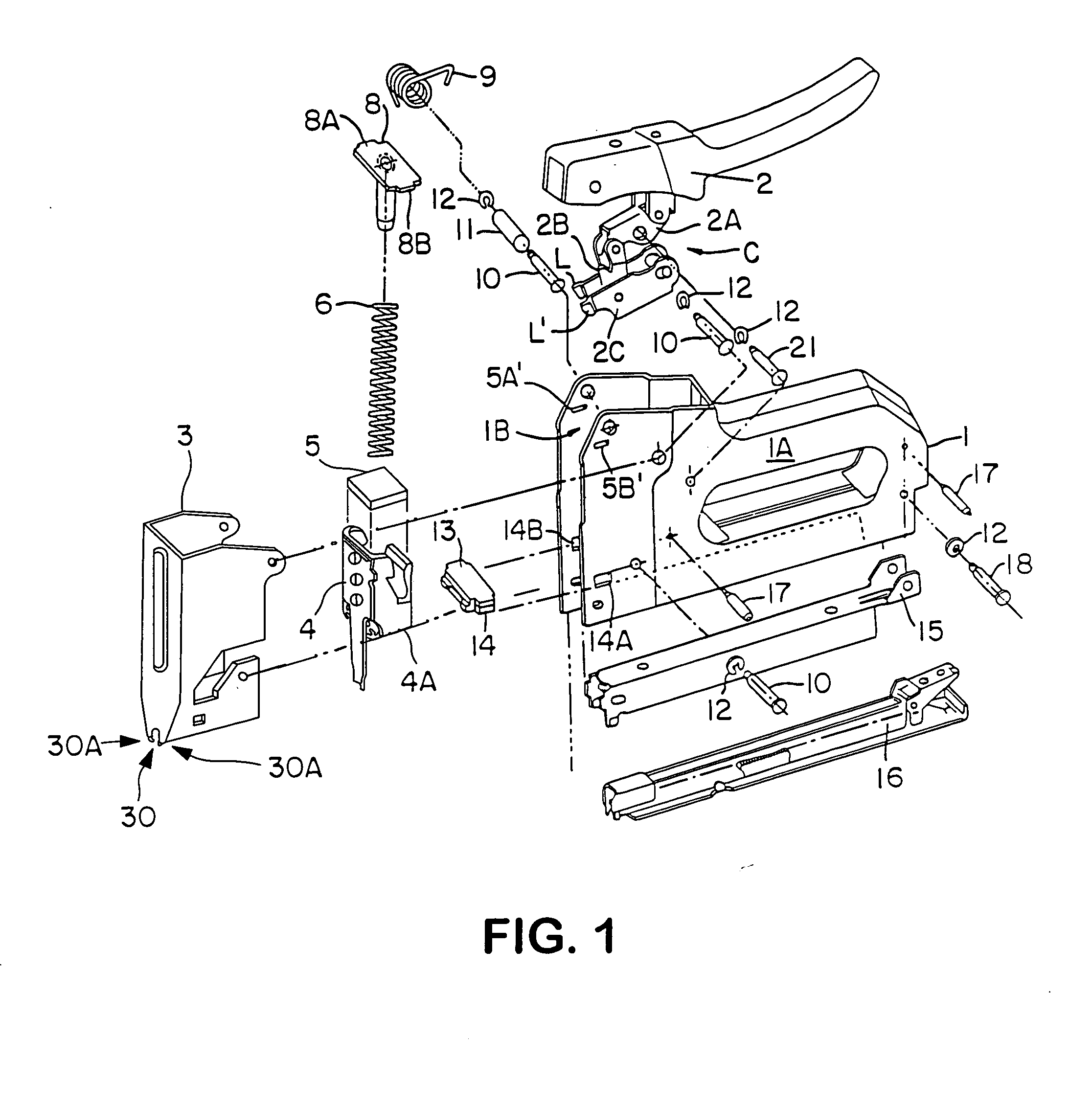
[0021] Turning first to FIG. 1, there is shown one embodiment of the present invention, which is a spring actuated staple gun adapted to drive U-shaped staples housed in a magazine into a surface or substrate. The gun includes a tool body 1 comprised of two stamped nickel-plated sheet metal sides 1A and 1B that form a housing there between. Alternatively, the housing could be a cast or molded body. Pivotally fixed to the underside of a handle 2 is a spring-loaded lever assembly C, substantially located in said housing, which includes extended link 2A and lifter 2C and allows the handle of the gun to be depressed to actuate the gun and released in order to reset the actuation mechanism. A handle return spring 9 is fixed to the handle 2. Spring retainer 8 has opposite flanges 8A, 8B that align with opposite slots 5A′5B′ in sides 1A and 1B of the tool body 1 to fix spring retainer 8 therein. A driver spring pad 5 aligns with the bottom of the driver spring 6 and sits in the body of dri...


PUM

PropertyMeasurementUnit
anglesaaaaaaaaaa
heightaaaaaaaaaa
heightaaaaaaaaaa

Abstract

Fastening tool for driving a fastener such as a staple into a substrate a predetermined distance. The tool includes a housing and a driver reciprocally mounted in the housing and moveable with respect to the housing, the driver having a driving surface for engaging a fastener such as a staple. A magazine assembly is associated with the housing for positioning and aligning the fastener in the path of the driver so that when actuated, the driver strikes the fastener and forcibly ejects it from the magazine into the substrate to a predetermined extent so as to adjust or control the holding power of the fastener about the object.

Description

[0001] This application is a continuation of U.S. Ser. No. 10 / 374,353 filed Feb. 25, 2003, the disclosure of which is hereby incorporated by reference.BACKGROUND OF THE INVENTION [0002] The present invention is directed towards a staple gun or fastener driving or applying tool for driving staples or other fasteners into surfaces. In particular, the present invention relates to a fastening tool where the stroke length of the driver is modified to reduce or eliminate the impact of the fastener on the object being fastened. [0003] Staple, nail, brad, screw and other fastener-driving applying tools for industrial, commercial and do-it-yourself (DIY) use are well known. Often such tools are used to secure cables, wires, tubing and the like to a substrate such as wood by driving the fastener into the substrate, the fastener thereby surrounding the cable, wire or tubing on three sides. However, the fastener being applied may at the time of application (due to the impact of the fastener) or...

Claims


Application Information

Patent Timeline
Patent Type & Authority Applications(United States)
IPC IPC(8): B25C5/02B25C5/06B25C5/11F16B15/00
CPCB25C5/0257B25C5/06B25C5/11Y10T29/49826F16B15/0092Y10T29/49947F16B15/0015
Inventor BOSWINKEL, ONNOHAYNES, ROBERT
Owner BOSWINKEL ONNO
Learn More