Automatic truss jig setting system

a truss jig and setting system technology, applied in the field of jig systems, can solve the problems of less time saving and reliable, high price of projection equipment and associated controlling system, and the environment in which the jig system is used, so as to avoid frequent cleaning and sudden breakdown of the apparatus and improve the ability of the system to handl

Inactive Publication Date: 2005-06-09
COLUMBIA INSURANCE CO
View PDF46 Cites 34 Cited by
  • Summary
  • Abstract
  • Description
  • Claims
  • Application Information

AI Technical Summary

Benefits of technology

[0022] One significant advantage of the present invention is the ability to minimize, if not altogether prevent, the buildup of debris on (or in the proximity of) the apparatus for moving the pin assemblies so that frequently cleaning and sudden breakdowns of the apparatus can be avoided. Another significant advantage is the ability of the system to handle situations where one of the pin assemblies is prevented from moving by an obstruction.

Problems solved by technology

Various approaches have been used to speed up the jig stop set up process, and one approach has been to project an image of the desired truss in actual shape and size on the surface of the jig, which can help minimize the amount of measurement required but does not eliminate the need to repeatedly secure and loosen the stops for each truss design.
Further, the projection equipment and associated controlling system tends to be relatively expensive.
While in concept these systems can save time otherwise needed to measure, move and secure the stops on the jig, there have been problems that have cropped up with these systems that make them less time saving and reliable as they could be for optimum efficiency.
For example, the environment in which the jig systems are used is filled with debris and dust.
As each puck is typically mounted on a screw-threaded rod that is positioned below the puck in the slot, the debris often falls onto the rod.
Since the rod rotates to move the puck, a rod caked with debris can hamper and even prevent movement of the puck along the rod.
Further complicating this situation is the fact that the screw-threaded rods typically are covered with some type of lubricant to facilitate movement of the puck along the rod, and this often sticky lubricant holds the debris on the surface of the rod.
The encrusted rod can carry the debris into the cooperating parts of the system, and cause additional friction and failure.
Still further exacerbating this problem in the known systems is the placement of the rod in a channel located below the slot with a closed bottom that holds the debris in close proximity to the rod, so that infrequent clearing of the channels can bring debris in contact with the rods from the bottom (as well as from the top as debris falls from the table surface).
Also, the known systems lack a suitable system for dealing with encounters between the puck and an obstruction while the puck is moving to the desired position.
Some known systems permit slippage between the driving motor and the rod when resistance in moving the puck is encountered, but the slippage results in the system losing track of the position of the puck on the jig and the system must then be reset in some manner so that the system can reassess the position of the puck on the table and reposition each of the affected pucks to the correct positions.
This is particularly a problem in systems that rely upon the precise rotation of the motor (such as a stepper motor) in order to determine the current position of the puck on the jig system.
Any slippage between the motor and the rod results in the puck being in a position different from where the system registers the location of the puck.
This requirement can make it difficult to retrofit previously constructed tables, or newly built tables that include significant support structure below the table segments.
Thus, while the known systems for automatically positioning the stops on the jig are an improvement over jig systems requiring manual positioning of the stops, there are significant new problems that have arisen with the use of these automatic systems that hamper their operation in a highly efficient and effective manner.

Method used


Image

  • Automatic truss jig setting system
  • Automatic truss jig setting system
  • Automatic truss jig setting system

Examples


Embodiment Construction

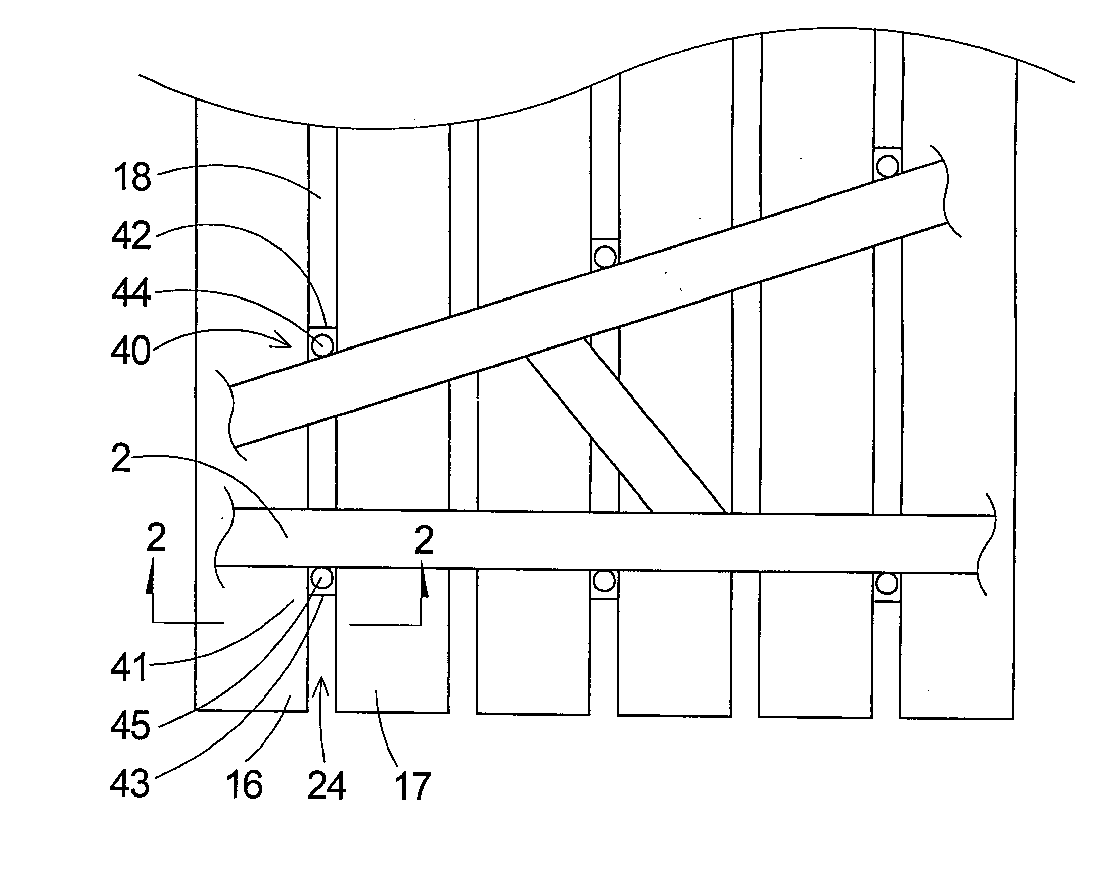
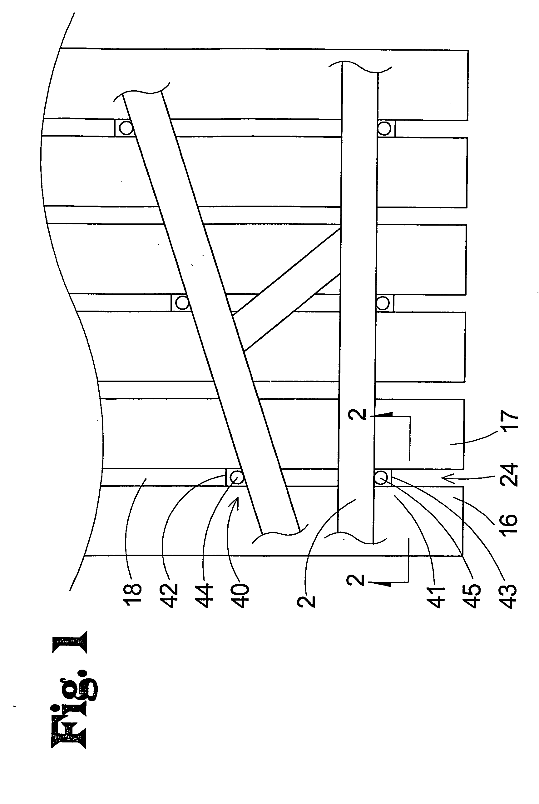
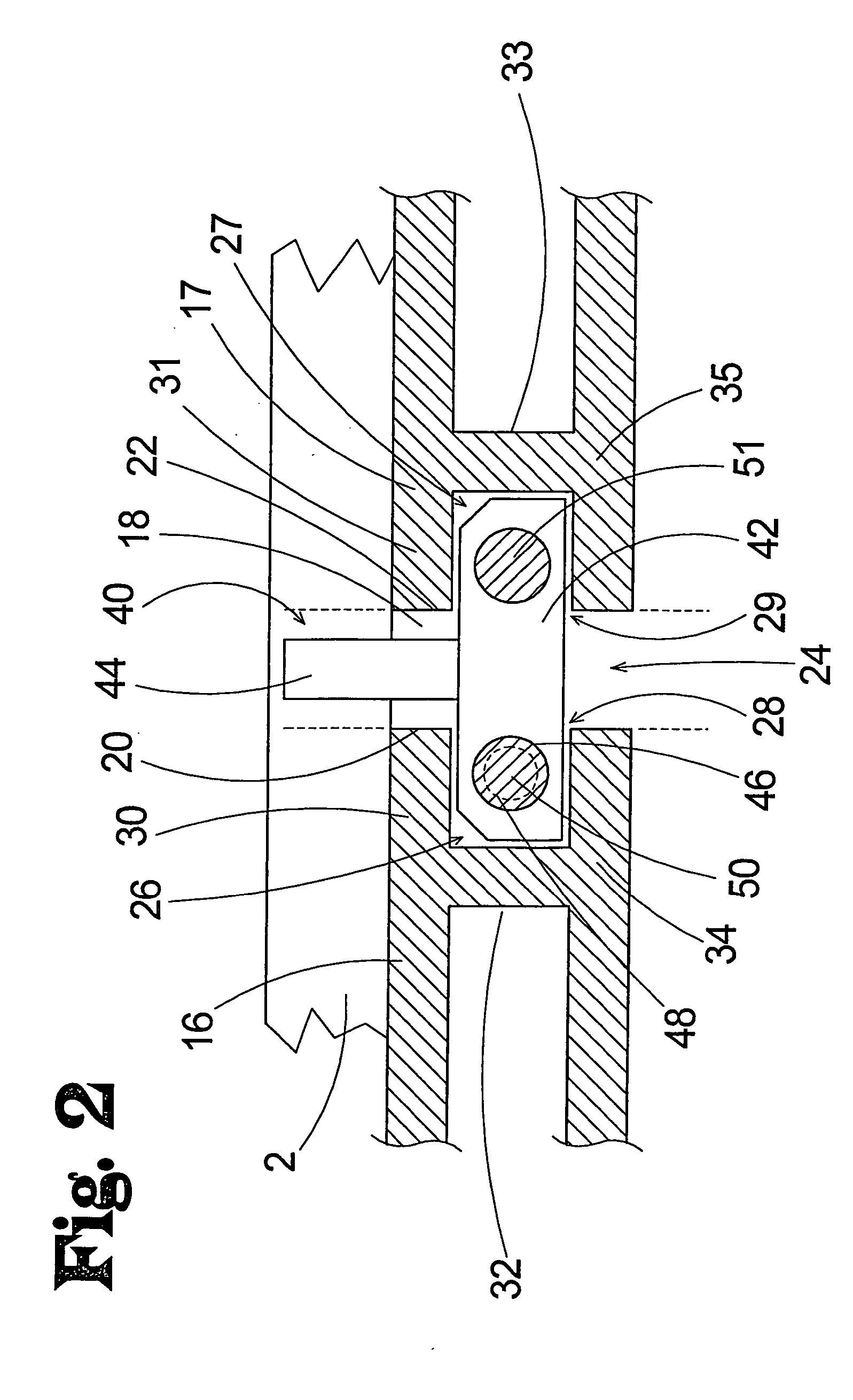
[0035] With reference now to the drawings, and in particular to FIGS. 1 through 10 thereof, a new automatic truss jig setting system embodying the principles and concepts of the present invention and generally designated by the reference numeral 10 will be described.

[0036] As best illustrated in FIGS. 1 through 8, the truss jig positioning system 10 of the invention may suitably be employed on a table 12 that has and defines a support plane 14 on which work pieces or building elements (such as wood boards or other building materials) are supported in proper position for forming a structure such as a support truss for a roof of a building. The table 12 may comprise a plurality of segments 16 that have upper surfaces 15 that substantially lie in and define the support plane 14 of the table. The upper surface of each of the segments may be substantially planar, and a plane of the segments may be oriented substantially horizontal.

[0037] The segments 16 of the table are separated by sl...


PUM

PropertyMeasurementUnit
movementaaaaaaaaaa
sizeaaaaaaaaaa
timeaaaaaaaaaa

Abstract

A automatic truss jig setting system is disclosed that includes a table including a plurality of segments with a side edge of adjacent segments defining a slot. At least one pin assembly, and optionally a pair of pin assemblies, is movable independently of each other along the slot. Movement apparatus is provided for independently moving the pin assemblies along the slot. Each of the side edges of the segments associated with the slot defines a substantially vertical plane with a zone being defined between the substantially vertical planes of the side edges, and the movement apparatus is located substantially outside of the zone of the slot. The invention may optionally include a system for handling the obstruction of pin assembly movement, and a system for keeping track of the position of the pin assembly when the pin assembly has encountered an obstruction.

Description

REFERENCE TO RELATED APPLICATION [0001] This application is a continuation-in-part of U.S. patent application Ser. No. 10 / 780,477, filed Feb. 17, 2004, which is a continuation of U.S. patent application Ser. No. 10 / 369,038, filed Feb. 18, 2003, now U.S. Pat. No. 6,712,347.BACKGROUND OF THE INVENTION [0002] 1. Field of the Invention [0003] The present invention relates to jig systems and more particularly pertains to a new automatic truss jig setting system for setting and resetting jig stops in a highly efficient and effective manner. [0004] 2. Description of the Prior Art [0005] Jig systems have been used to hold building elements, such as wood boards, in proper position while the building elements are attached to each other to construct a roof support truss. Known jig systems typically employ a horizontal surface (such as a table) for resting the building elements thereon and a plurality of adjustable stops for indicating the proper positions of the building elements in the desire...

Claims


Application Information

Patent Timeline
Patent Type & Authority Applications(United States)
IPC IPC(8): B27F7/15
CPCB25B11/02Y10S269/91B27F7/155Y10T29/5397B25B1/20
Inventor FREDRICKSON, CLYDE R.WISMER, MARK
Owner COLUMBIA INSURANCE CO
Why Eureka
Try Eureka