Backer strip load distribution device for a support structure

a technology of supporting structure and load distribution device, which is applied in the direction of bumpers, curb suspension devices, furniture parts, etc., can solve the problems of large force being imparted upon the shelving, indentations or similar damage to the wall portions engaged by the supporting structure, and items supported by the shelving can be relatively heavy, so as to increase the load distribution capacity and save manual assembly time , the effect of increasing the surface area of engagemen

Active Publication Date: 2011-01-06
BUSCH CHARLES D
View PDF13 Cites 1 Cited by
  • Summary
  • Abstract
  • Description
  • Claims
  • Application Information

AI Technical Summary

Benefits of technology

[0011]Another object of the present invention is to provide a device that is removably secured to a support structure via means external to the support structure. A feature of the device is opposite deformable securing arms integrally joined to side walls of the load distribution member. An advantage of the device is that the securing arms can be manually separated a distance that allows the support structure to engage the load distribution member, whereupon, the securing arms are manually released to “spring” back to engage outer side walls of the support structure, thereby saving manual assembly time for joining together the support structure and the device.
[0012]Another object of the present invention is to provide a device that has increased load distribution capabilities. A feature of the device is an alignment member that engages an inner top wall of the support structure. An advantage of the device is that more surface area of engagement is provided between the support structure and the device, thereby better distributing a force across a wall portion surface area to prevent indenting or damage to the wall portion.
[0013]Other objects of the present invention are to provide a device that is easy to install, easy to assembly with a support structure, easy to cut, symmetrically disposed the support structure upon a load distribution member, adapts to wall surface non-planar irregularities, prevents debris build-up, increases a load distribution area, permits unobstructed slotting of brackets upon the support structure, and that has low manufacturing costs.
[0014]Briefly, the invention provides a backer strip load distribution device for a support structure secured to a wall portion comprising a load distribution member disposed between a support structure and a wall portion; an alignment member for disposing the support structure upon a predetermined portion of said load distribution member; means for securing said load distribution member to the support structure; and means for securing the support structure to the wall portion while said load distribution member is secured to the support structure without said load distribution member obstructing the securing of the support structure to the wall portion, whereby, a backer strip load distribution device is provided that secures to the support structure such that said backer strip load distribution device is disposed between the support structure and the wall portion, thereby preventing engagement of the support structure upon the wall portion and resulting in a distribution of a load from the support structure upon said backer strip load distribution device such that the wall portion is not damaged.
[0015]The invention further provides a support structure load distribution device comprising a substrate member secured to a support structure that is ultimately secured to a wall portion; an alignment member for disposing the support structure upon a predetermined portion of said substrate member; a securing member for securing the support structure to said substrate member; and means for preventing said substrate member from obstructing the securing of the support structure to the wall portion, whereby, said substrate member is ultimately secured between the support structure and the wall portion thereby preventing the support structure from damaging the wall portion due load bearing objects ultimately secured to the support structure.
[0016]The invention also provides a device for preventing a support structure from damaging a wall portion comprising a load distribution member for disbursing a load imparted upon the support structure; an alignment member for disposing the support structure upon a preselected portion of said load distribution member; and a securing member for removably joining the support structure to said load distribution member such that the support structure is allowed to be secured to a wall portion, whereby, said load distribution member is disposed between the support structure and the wall portion, thereby preventing the wall portion from being indented.

Problems solved by technology

The items supported by the shelving can be relatively heavy causing a large force to be imparted upon the shelving and correspondingly upon the brackets and support structures.
The problem with the prior art is that the large force imparted upon the support structures results in indentations or similar damage to wall portions engaged by the support structures.

Method used


Image

  • Backer strip load distribution device for a support structure
  • Backer strip load distribution device for a support structure
  • Backer strip load distribution device for a support structure

Examples


Embodiment Construction

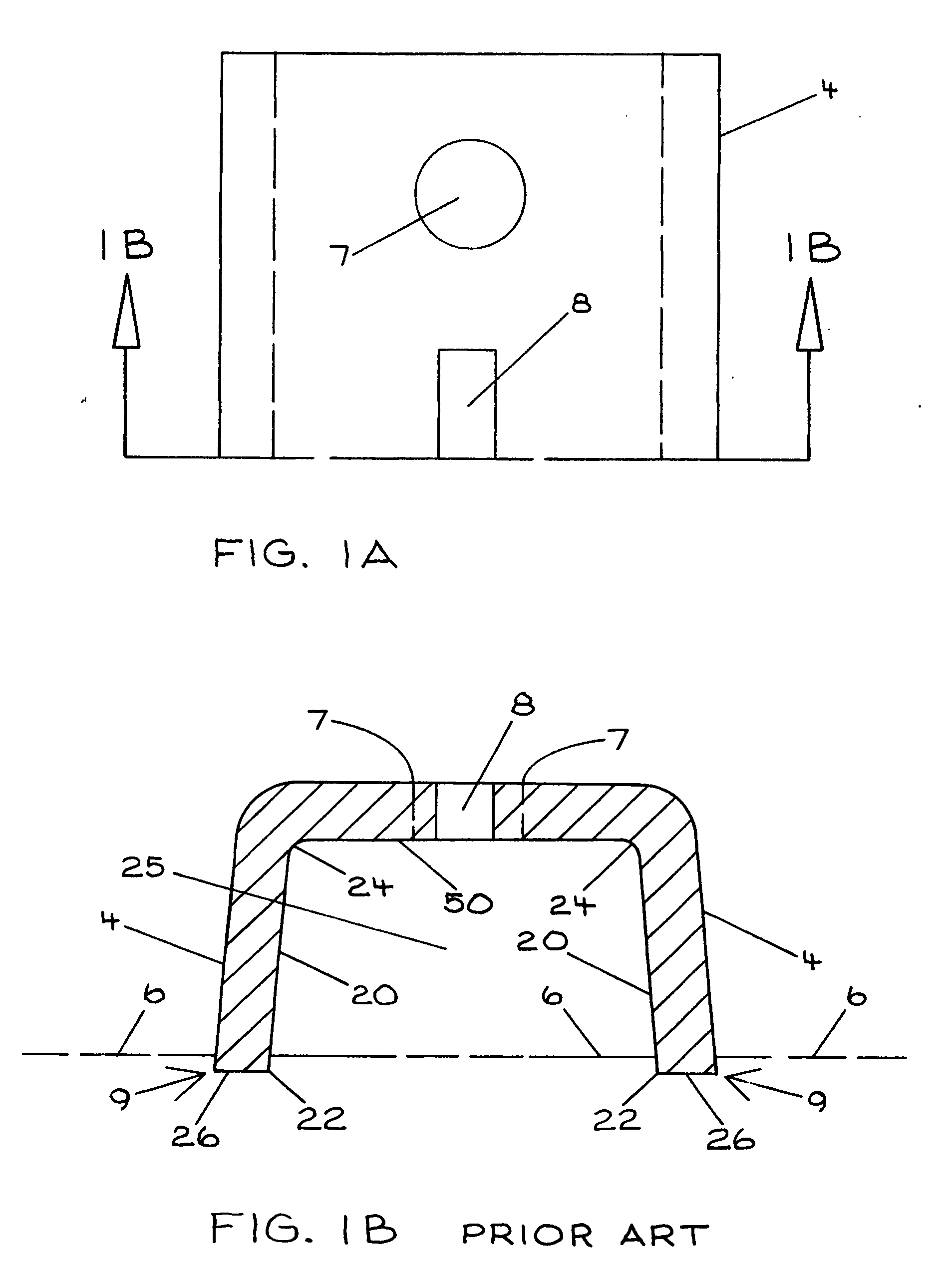
[0045]Referring now to the drawings, an in particular to FIGS. 1A and 1B (prior art), a typical support structure 4 is secured to a wall portion 6. The support structure 4 includes fastener receiving apertures 7 to promote the securing of the support structure 4 to the wall portion 6, and bracket slots 8 for removably receiving brackets (not depicted) that support shelving and other objects (not depicted) that impart a force or load upon the support structure 4. The force imparted upon the support structure 4 urges the support structure 4 into the wall portion 6, resulting in indented sections 9 of the wall portion 6 engaged by the support structure 4.

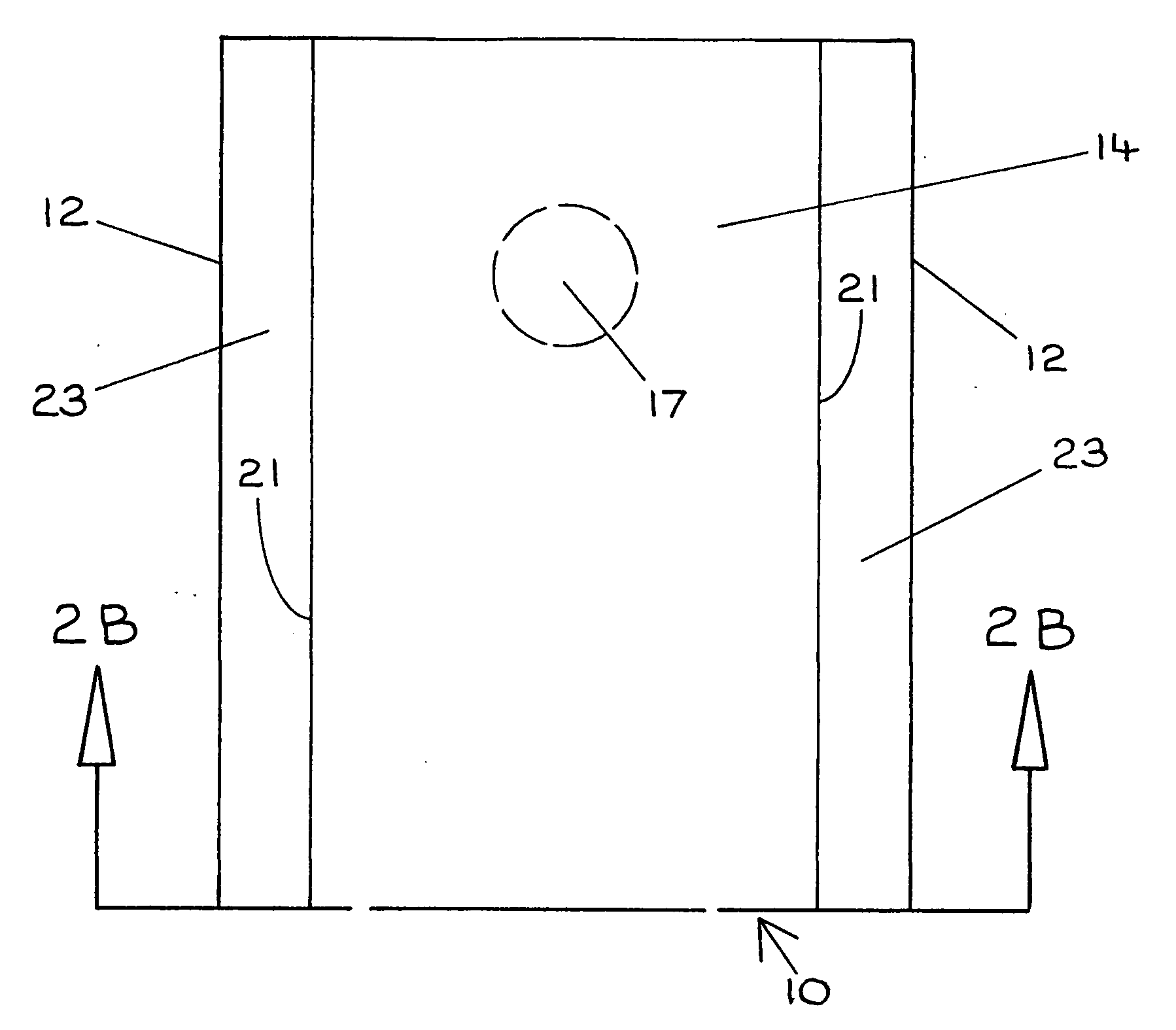
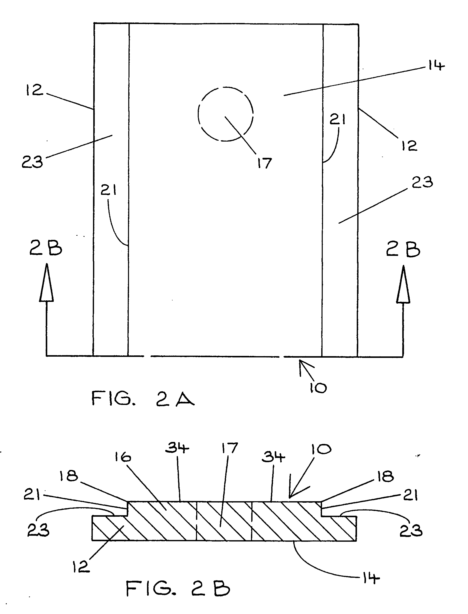
[0046]Referring now to FIGS. 2A, 2B and 3, a backer strip load distribution device for a support structure 4 ultimately secured to a wall portion 6 in accordance with the present invention is denoted as numeral 10. The device 10 includes a load distribution member 12 or substrate portion for disbursing a load imparted upon the device 1...


PUM


Abstract

A backer strip load distribution device 10 includes a load distribution member 12 for disbursing a load imparted upon the device 10 over an area of the wall portion 6 engaged by a back wall 14 of the distribution member 12. The device 10 also includes an alignment member 16 for disposing a support structure 4 (prior art) upon a preselected portion of the load distribution member 12.

Description

BACKGROUND OF THE INVENTION[0001]1. Field of the Invention[0002]The present invention relates generally to load distribution devices and, more particularly, to a load distribution strip removably secured to a wall engagement side of a support structure that is fastened to a wall portion, the support structure ultimately receiving the weight imparted from objects secured thereto.[0003]2. Background of the Prior Art[0004]Slotted support rails or similar structures are vertically fastened to walls to provide support structures for brackets that are removably secured to the support structure via slots longitudinally centered along the support structure. The brackets that are inserted into the slots are designed to receive shelving resulting in a book case configuration mounted to a wall. The items supported by the shelving can be relatively heavy causing a large force to be imparted upon the shelving and correspondingly upon the brackets and support structures.[0005]The problem with the...

Claims


Application Information

Patent Timeline
Patent Type & Authority Applications(United States)
IPC IPC(8): A47B96/06
CPCE04F13/0803A47B96/1458
Inventor BUSCH, CHARLES D.
Owner BUSCH CHARLES D
Why Eureka
Try Eureka