Photovoltaic module mounting system

Active Publication Date: 2010-09-02
COROSOLAR LLC
View PDF16 Cites 84 Cited by
  • Summary
  • Abstract
  • Description
  • Claims
  • Application Information

AI Technical Summary

Benefits of technology

[0020]The flexible foot, cruciform, and link structure provide a compliant mounting structure that can follow the contour of the mounting surface while simultaneously resisting the uplift and down push forces of wind loading. The link members, which in one embodiment may be made from pre-galvanized, roll formed steel, span the distance between the rubber pedestal feet. The feet provide the contact point with the mounting surface. In the case

Problems solved by technology

This gasket has small, finger like protrusions that allow for easy insertion onto the module e

Method used


Image

  • Photovoltaic module mounting system
  • Photovoltaic module mounting system
  • Photovoltaic module mounting system

Examples


Embodiment Construction

[0052]The following description is provided to enable any person skilled in the art to make and use the invention and sets forth the best modes contemplated by the inventor for carrying out the invention. Various modifications, however, will remain readily apparent to those skilled in the art. Any and all such modifications, equivalents and alternatives are intended to fall within the spirit and scope of the present invention.

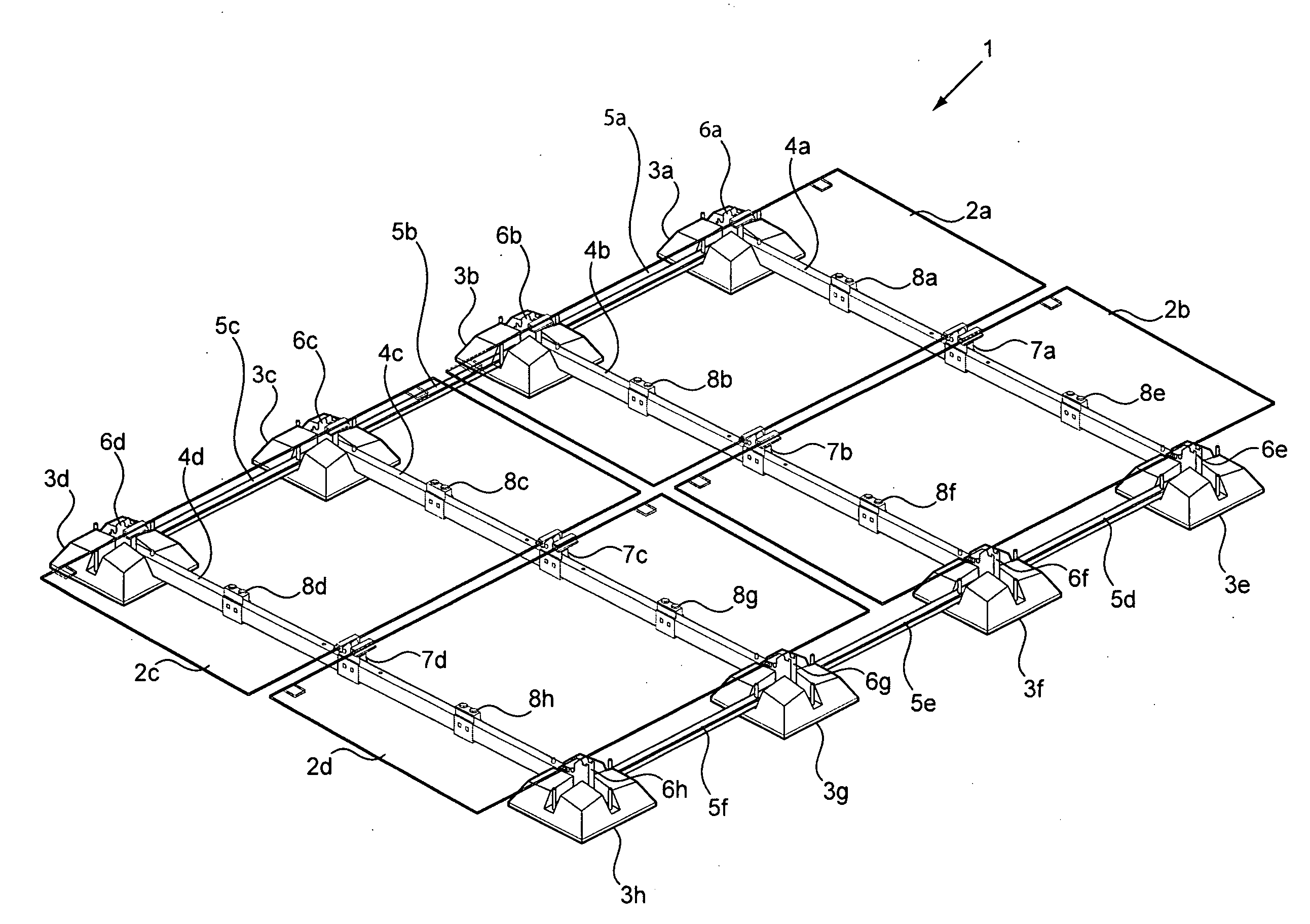
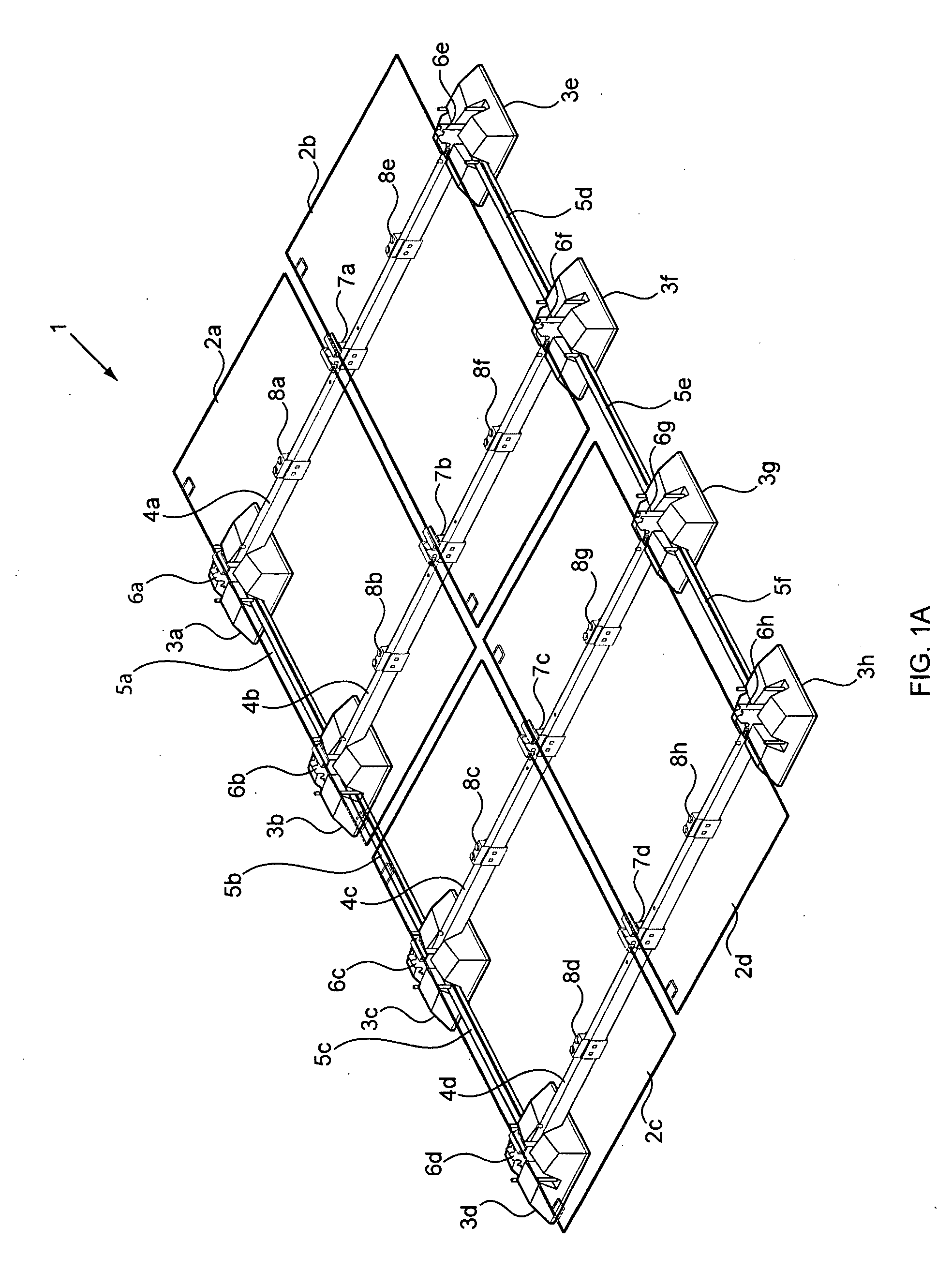
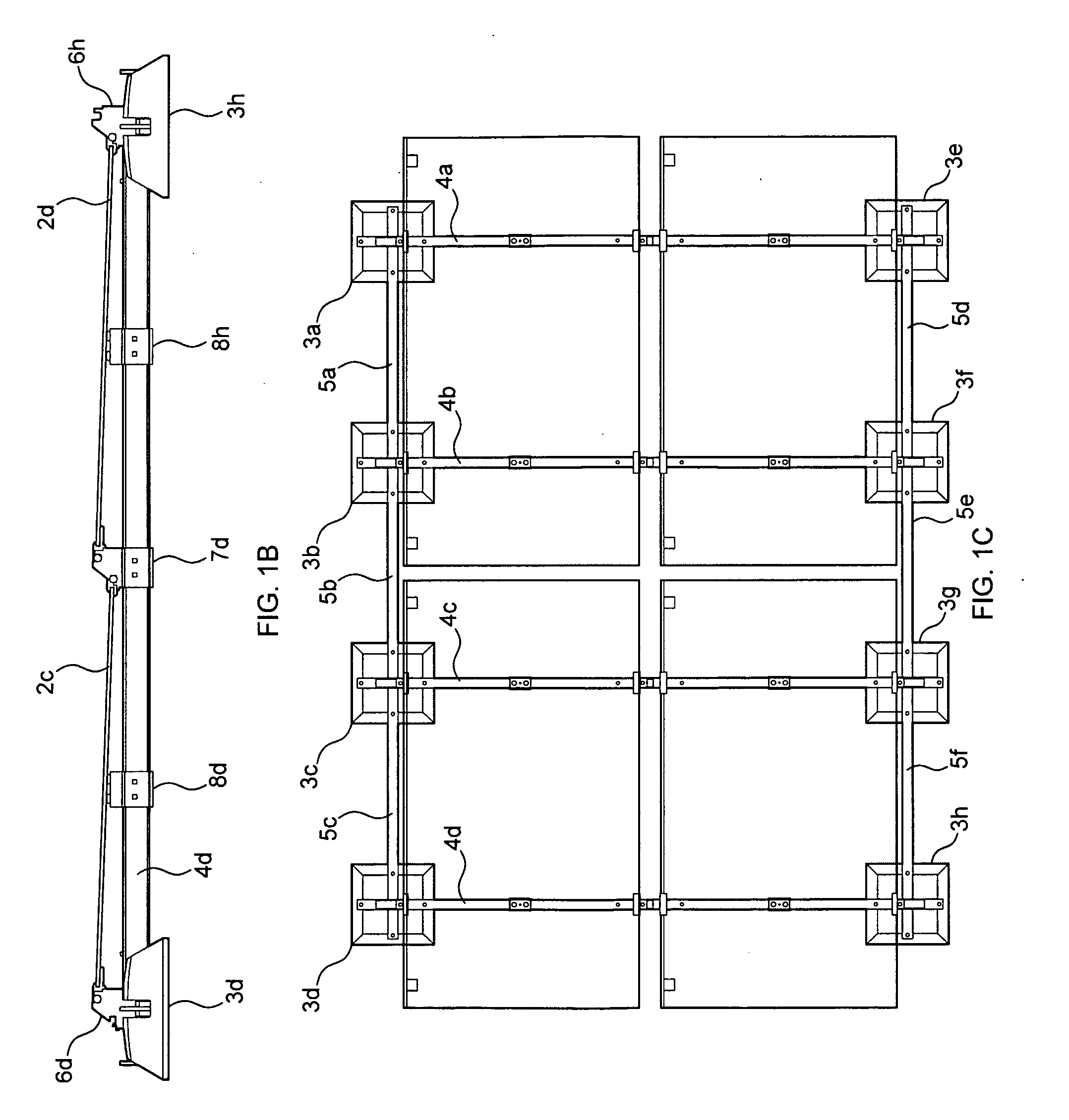
[0053]FIGS. 1A-1D illustrate the basic components and arrangement of the solar array mounting system according to an embodiment of the present invention. FIG. 1A is a perspective view of a solar panel mounting system 1 according to an embodiment of the present invention. Four photovoltaic solar panels 2a-2d are mounted on the mounting structure. The solar panels 2a-2d can be “frameless” panels formed as laminates of two sheets of glass encasing photovoltaic material. For example, the panels 2a-2d may be photovoltaic “thin film” panels. The mounting system 1 inc...


PUM


Abstract

A solar array mounting system having unique installation, load distribution, and grounding features, and which is adaptable for mounting solar panels having no external frame. The solar array mounting system includes flexible, pedestal-style feet and structural links connected in a grid formation on the mounting surface. The photovoltaic modules are secured in place via the use of attachment clamps that grip the edge of the typically glass substrate. The panel mounting clamps are then held in place by tilt brackets and/or mid-link brackets that provide fixation for the clamps and align the solar panels at a tilt to the horizontal mounting surface. The tilt brackets are held in place atop the flexible feet and connected link members thus creating a complete mounting structure.

Description

[0001]This invention was made with U.S. Government support under Contract No. DE-FC36-07GO17047 awarded by the Department of Energy. The Government has certain rights in this invention.BACKGROUND OF THE INVENTION[0002]1. Field of the Invention[0003]The present invention relates generally to a system for mounting and installing photovoltaic solar panels, and more particularly, to a photovoltaic solar panel mounting support system providing enhanced attachment features for solar panels having no external frame.[0004]2. Description of the Related Art[0005]With the continual rise in conventional energy costs, photovoltaic solar panels (“PV panels”) are increasingly becoming cost competitive with other types of energy generation. These PV panel systems are being installed in sites of high energy usage, such as on commercial building rooftops, in industrial open areas, and in proximity to substations tied to the electric grid. These commercial energy systems, or power plants, vary in size...

Claims


Application Information

Patent Timeline
IPC IPC(8): F16M11/24F16M11/04F16M11/22
CPCF24J2/5205F24J2/5239F24J2/5245F24J2/525F24J2/5258F24J2002/5281H02S20/24Y02B10/12Y02E10/47Y02E10/50H02S20/00H02S30/10F24J2002/5292F24S25/16F24S25/33F24S25/61F24S25/617F24S25/636F24S2025/014F24S2025/02H02S40/36Y02B10/10
Inventor MIROS, ROBERT H.J.MITTAN, MARGARET BIRMINGHAMSEERY, MARTIN N.HOLLAND, RODNEY H.
Owner COROSOLAR LLC
Why Eureka
Try Eureka