Lighting device

a technology of light emitting diodes and lighting devices, which is applied in outdoor lighting, lighting heating/cooling arrangements, electric variable regulation, etc., can solve the problems of low light output, low maintenance efficiency, and low use value of lighting devices, and achieves a fraction of the cost of leds of typical hid lamps

Inactive Publication Date: 2005-06-09
GESTION PROCHE
View PDF18 Cites 71 Cited by
  • Summary
  • Abstract
  • Description
  • Claims
  • Application Information

AI Technical Summary

Benefits of technology

[0066] a dirt detection means being configured to detect the amount of dirt on the outer surface of the lighting device and communicating this amount to the calculation means so that the calculation means may compensate for the dirt by increasing the light provided by the lighting device.

Problems solved by technology

A problem with current tunnel lighting lamps is with lifespan.
In a typical tunnel lamp which uses one or maybe two illumination sources, the lighting device can easily become unuseable should the illumination source break down.
Thus maintenance of lighting devices can become costly and time consuming.
While an individual LEDs is on its own not sufficient to provide lighting for a tunnel, LEDs only cost a fraction of what a typical HID lamp would cost.
They do, however, not have features which allow for a constant luminosity to be maintained over an extended lifespan.
In the context of roadway or tunnel lighting, the use of PWM to control the LED intensity may be problematic.

Method used


Image

  • Lighting device
  • Lighting device
  • Lighting device

Examples


Embodiment Construction

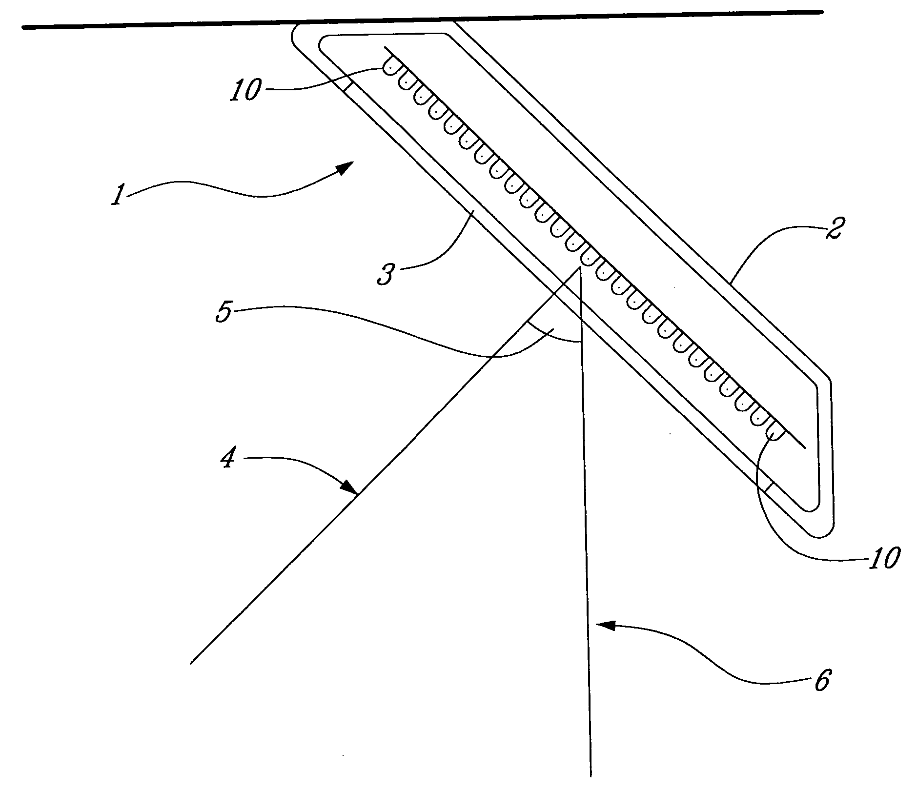
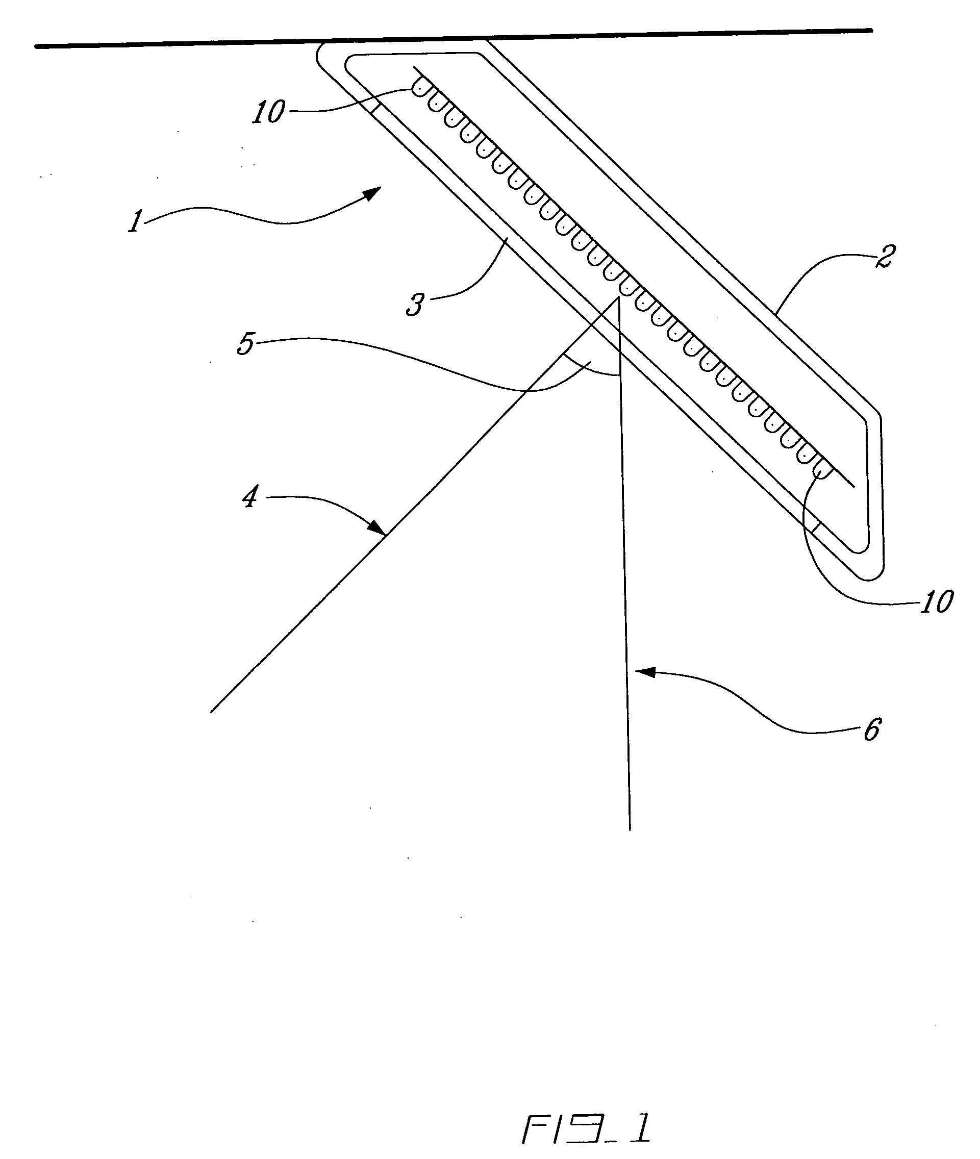
[0099]FIG. 1 shows a: lighting device 1 of the invention, having a lighting device casing 2 with a transparent face 3 in front of a LED array 10. To ensure long-term reliability the casing 2 is environmentally sealed, so that dust and water cannot penetrate inside.

[0100] The casing 2 has a shape such that when the lighting device 1 is installed in its normal position (e.g. on the ceiling of a tunnel facing downwards), its light emission axis 4 is tilted by an angle 5 from the vertical axis 6, towards the incoming traffic. This angle 5 can range from −90 to +90 degrees (e.g. 0 to 80 degrees). Light distribution simulations show that having the angle 5 in the range of 60 to 70 degrees allows for optimization of the illuminance. It should of course be noted that any sufficient angle may be used.

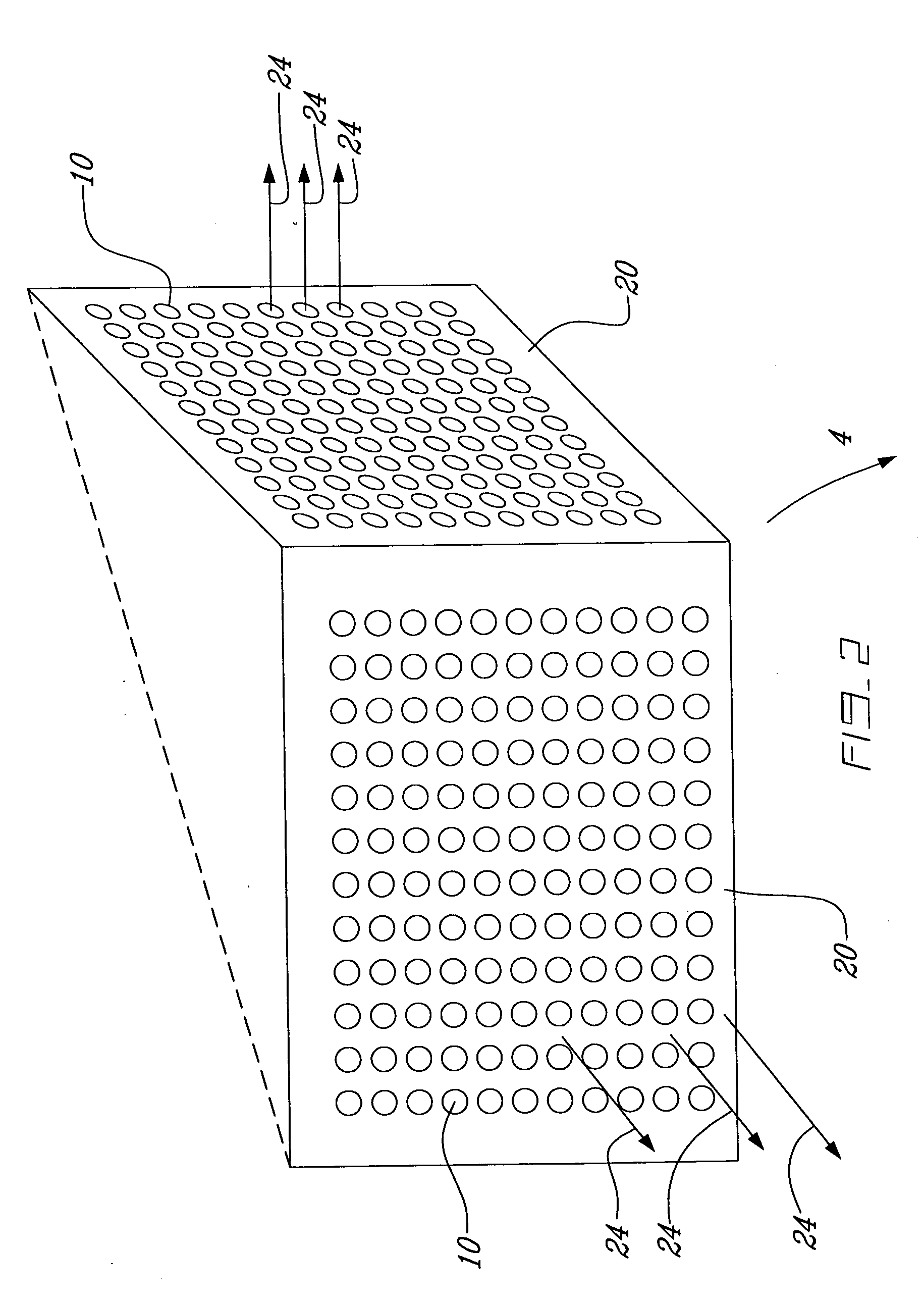
[0101] In the embodiment of the invention shown in FIG. 2, the lighting device 1 has as its main illumination source of an array of individual LEDs 10. The LEDs 10 are assembled on one or more...


PUM


Abstract

An LED lighting device is provided which is capable of being connected to a network and being controlled by a host computer also connected to the network. The lighting device has several lifespan expanding features such as including several extra LEDs such that as the LEDs of the lighting device degrade over time more LEDs can be turned on thus allowing a constant luminosity to be maintained.

Description

BACKGROUND OF THE INVENTION [0001] The current invention is an light emitting diode (herein referred to as LED) lighting device having multiple features designed to allow the lighting device to maintain luminosity as measured in candelas, over its lifespan. The invention is also designed so that multiple lighting devices can be connected in a network controlled by a host computer, such that the general luminosity over an area (e.g. a tunnel) can be controlled. [0002] Traditionally, roads and tunnel lighting devices have used uses HID (High-Intensity Discharge) lamps, powered with high-voltage (e.g. 300 VAC to 400 VAC). [0003] Existing roadway standards divide the length of the tunnel into a number of regions. Each region requires a lighting intensity (sometimes herein referred to as luminosity) that increases as it is nearer the entrance / exit points (because of the presence of higher illumination from the sun), and decreases towards the middle of the tunnel. As an example, a typical...

Claims


Application Information

Patent Timeline
Patent Type & Authority Applications(United States)
CPCF21S8/04F21W2131/101F21Y2101/02F21Y2105/001H05B33/0803H05B33/0827F21V29/763H05B33/0851H05B33/0893H05B37/0245H05K1/14Y02B20/48H05B33/0842F21Y2105/10F21Y2115/10H05B45/58H05B45/46H05B47/20Y02B20/40H05B45/30H05B45/12H05B47/175
Inventor CHEVALIER, DANIELMARTEL, ALAIN
Owner GESTION PROCHE
Why Eureka
Try Eureka