Electro-optical display device and image projection unit
- Summary
- Abstract
- Description
- Claims
- Application Information
AI Technical Summary
Benefits of technology
Problems solved by technology
Method used
Image

Examples
first embodiment
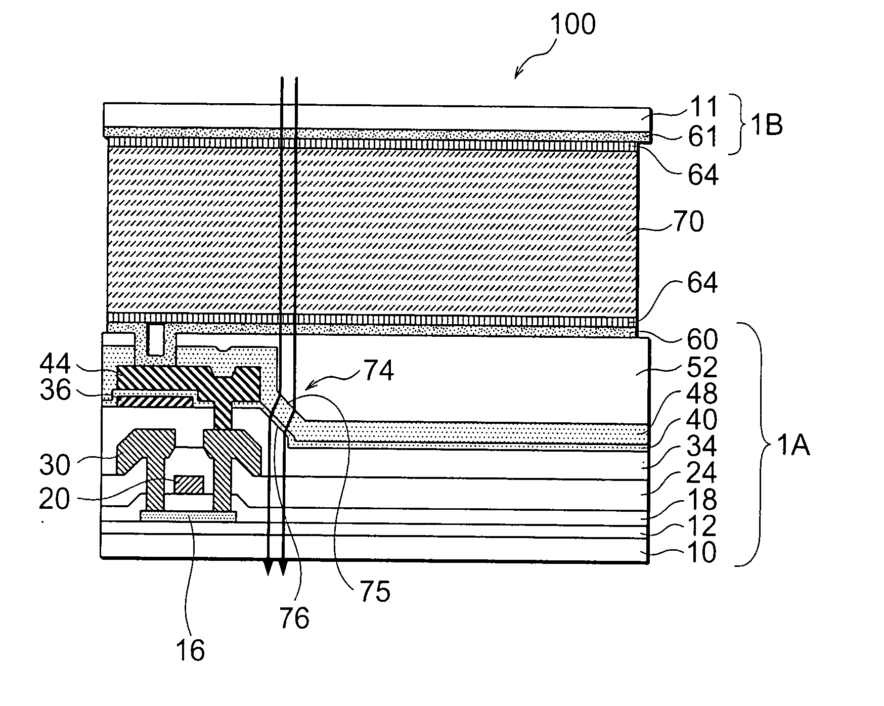
[0041] Referring to FIG. 1, a transmission LCD device, generally designated by numeral 100, according to the electro-optical display device of the present invention, includes a TFT substrate 1A and a counter substrate 1B sandwiching therebetween an LC layer 70. The TFT substrate 1A includes a glass substrate body 10, and a base layer 12 made of silicon oxide formed on the glass substrate body 10 and having a thickness of 0.06 to 0.03 μm. The base layer 12 has a function of preventing TFTs formed thereon from being stained by impurities diffused from the glass substrate body 10.
[0042] The TFTs formed on the base layer 12 each includes a polysilicon layer 16 acting as an active layer for the TFT, a gate electrode formed as a part of gate line 20, and a gate insulation film 18 formed between the polysilicon layer 16 and the gate line 20. The gate line 20 is made of WSi, Cr or Al, for example. The gate insulation film 18 is made of silicon oxide having a thickness of 0.1 μm. A portion o...
second embodiment
[0067] Referring to FIG. 4, a transmission LCD device, generally designated by numeral 200, according to the present invention is similar to the LCD device of FIG. 1 except for the layered structure. More specifically, in the LCD device of the present embodiment, the capacitor shown in FIG. 1 is not formed, and the third interlayer dielectric film 48 is formed directly on the second interlayer dielectric film 34. A through hole is formed penetrating the organic planarization film 52, the third interlayer dielectric film 48 and the second interlayer dielectric film 34 to reach the source / drain line 30. The pixel electrode 60 is formed on the organic planarization film 52 and in the through hole.
[0068] In the counter substrate 1B, a shield film pattern 44 is formed to shield the TFT area in the TFT substrate 1A, replacing a portion of the orientation film 64. Other configurations of the LCD device 200 are similar to those of the LCD device 100 of FIG. 1.
[0069]FIGS. 5J to 5M show fabr...
third embodiment
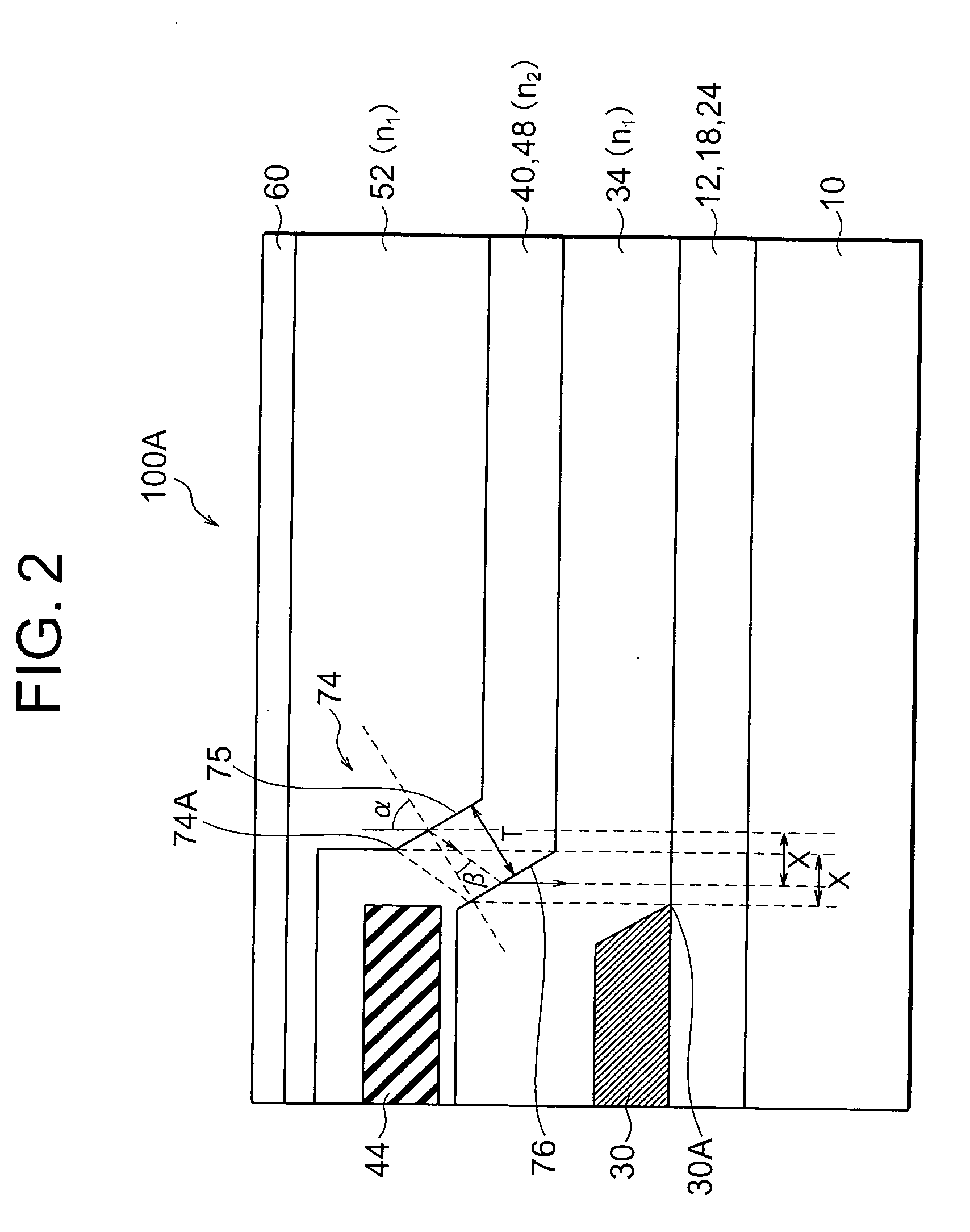
[0073] Referring to FIG. 6, a TFT substrate 3A of a transmission LCD device according to the present invention is such that portions of the third interlayer dielectric film 48 and the capacitor insulation film 40 located within the opening area, or inner side of the slope area 74, are removed by etching. On the portion of the second interlayer dielectric film 34 exposed by the removal of the third interlayer dielectric film 48 and on the remaining portion of the third interlayer dielectric film 48, there is provided an organic planarization film 52 made of silicone resin. The organic planarization film 52 has a flat top surface parallel to the surface of the glass substrate body 10. The organic planarization film 52 has a refractive index of about 1.4 to 1.5, which is equivalent to the refractive index of the glass substrate body 10 and the silicon oxide. A through hole 56 is formed penetrating the organic planarization film 52 and the third interlayer dielectric film 48 to reach th...
PUM
 Abstract
Description
Claims
Application Information
 - R&D
- Intellectual Property
- Life Sciences
- Materials
- Tech Scout
- Unparalleled Data Quality
- Higher Quality Content
- 60% Fewer Hallucinations
Browse by: Latest US Patents, China's latest patents, Technical Efficacy Thesaurus, Application Domain, Technology Topic, Popular Technical Reports.
© 2025 PatSnap. All rights reserved.Legal|Privacy policy|Modern Slavery Act Transparency Statement|Sitemap|About US| Contact US: help@patsnap.com